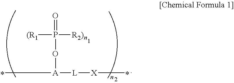
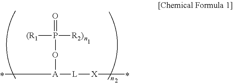
Hardmask composition, method of forming a pattern using the same, and semiconductor integrated circuit device including the pattern
a technology of semiconductor integrated circuits and masks, applied in the direction of photosensitive materials, instruments, photomechanical devices, etc., can solve the problem that the resist layer may not provide sufficient resistan
- Summary
- Abstract
- Description
- Claims
- Application Information
AI Technical Summary
Benefits of technology
Problems solved by technology
Method used
Image
Examples
synthesis example 1
[0118]76.4 g (0.35 mol) of 1-pyrenemethanol and 35.6 g of trioxane were dissolved in 182 g of 1,4-dioxane while inflowing nitrogen gas into a 500 ml, 4-neck flask equipped with a mechanical agitator, a condenser, and a nitrogen gas injecting tube to provide a solution, and the solution was agitated and reacted. After completing the reaction, the solution was condensed by an evaporator after removing acid using water. Subsequently, it was diluted using methanol to provide a solution with a concentration of 15 wt %. The solution was introduced into a 1 L separatory funnel and n-heptane was added to remove reaction side-products and to provide a polymer.
[0119]35 g of the obtained polymer and 10.65 g of diphenylphosphinic chloride were dissolved in 210 g of tetrahydrofuran (THF) while inflowing nitrogen gas into a 500 ml, 4-neck flask equipped with a mechanical agitator, a condenser, and a nitrogen gas injecting tube to provide a solution. The solution was agitated and reacted. After co...
synthesis example 2
[0122]76.4 g (0.35 mol) of 1-pyrenemethanol and 35.6 g of trioxane were dissolved in 182 g of 1,4-dioxane to provide a solution while inflowing nitrogen gas into a 500 ml, 4-neck flask equipped with a mechanical agitator, a condenser, and a nitrogen gas injecting tube, and the solution was agitated and reacted. After 15 minutes, 9.32 g (0.049 mol) of pyridinium p-toluene sulfonate was slowly added into the solution and reacted at 100° C. for 12 hours. After completing the reaction, the solution was condensed by an evaporator after removing acid using water. It was diluted using methanol to provide a solution with a concentration of 15 wt %. The solution was introduced into a 1 L separatory funnel and n-heptane was added to remove reaction side-products and to provide a polymer.
[0123]35 g of the obtained polymer and 5.06 g of diphenylphosphinic chloride were dissolved in 181 g of tetrahydrofuran (THF) while inflowing nitrogen gas into a 500 ml, 4-neck flask equipped with a mechanical...
synthesis example 3
[0126]22.5 g (0.20 mol) of dimethylphosphonic chloride and 28.8 g of 2-naphthol were dissolved in 680 g of dichloromethane to provide a solution while inflowing nitrogen gas into a 1000 ml-4-neck flask equipped with a mechanical agitator, a condenser, and a nitrogen gas injecting tube, and the solution was agitated and reacted. After 15 minutes, 24.29 g of triethylamine was slowly introduced into the solution and reacted for 12 hours. After completing the reaction and removing salt using water and dichloromethane, the solution was condensed by an evaporator to provide a solution with a concentration of 20 wt %. The solution was introduced into a 1 L separatory funnel and precipitated by adding n-heptane to provide a polymer.
[0127]37.4 g of the obtained polymer and 12.2 g of paraformaldehyde were dissolved in 120 g of propyleneglycol monomethylether acetate (PGMEA) while inflowing nitrogen gas into a 500 ml, 4-neck flask equipped with a mechanical agitator, a condenser, and a nitroge...
PUM
| Property | Measurement | Unit |
|---|---|---|
| wavelength region | aaaaa | aaaaa |
| wavelength region | aaaaa | aaaaa |
| polydispersity | aaaaa | aaaaa |
Abstract
Description
Claims
Application Information
 - R&D
- Intellectual Property
- Life Sciences
- Materials
- Tech Scout
- Unparalleled Data Quality
- Higher Quality Content
- 60% Fewer Hallucinations
Browse by: Latest US Patents, China's latest patents, Technical Efficacy Thesaurus, Application Domain, Technology Topic, Popular Technical Reports.
© 2025 PatSnap. All rights reserved.Legal|Privacy policy|Modern Slavery Act Transparency Statement|Sitemap|About US| Contact US: help@patsnap.com


