Semiconductor device
a semiconductor and device technology, applied in semiconductor devices, electronic switching, pulse techniques, etc., can solve the problems of large harmonic distortion, high parasitic capacitance of low-cost silicon substrates, and high cost of compound semiconductor substrates with excellent rf characteristics, so as to reduce the cost of antenna switches and minimize harmonic distortion generated in antenna switches.
- Summary
- Abstract
- Description
- Claims
- Application Information
AI Technical Summary
Benefits of technology
Problems solved by technology
Method used
Image
Examples
first embodiment
Structure and Operation of Mobile Phone
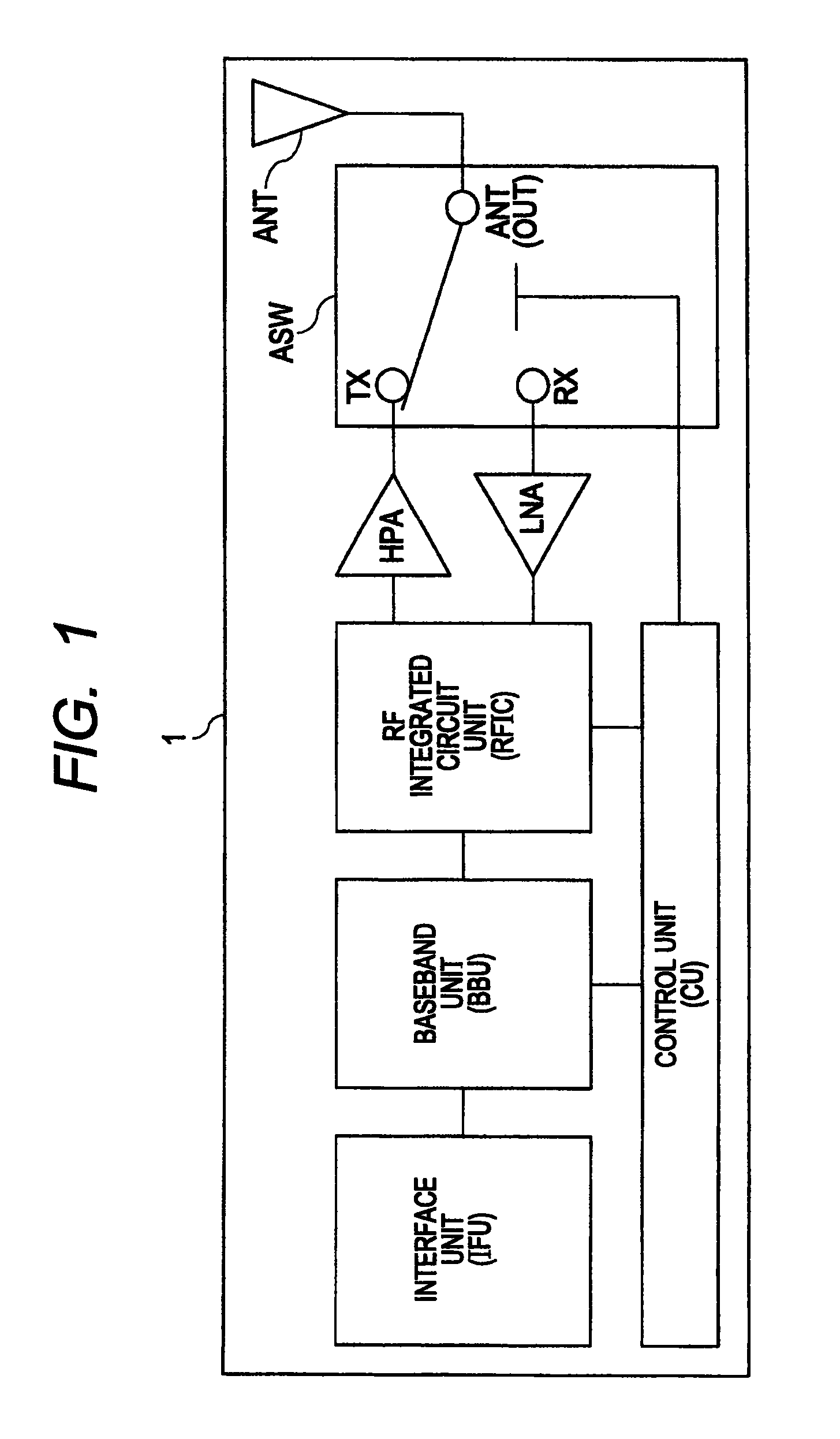
[0057]FIG. 1 is a block diagram showing a structure of the transmission / reception unit of a mobile phone. As shown in FIG. 1, a mobile phone 1 has a control unit CU, an interface unit IFU, a baseband unit BBU, an RF integrated circuit unit RFIC, a power amplifier HPA, a low noise amplifier LNA, an antenna switch ASW, and an antenna ANT.
[0058]The interface unit IFU has the function of processing an audio signal from a user (caller). That is, the interface unit IFU has the function of providing an interface between the user and the mobile phone. The baseband unit BBU has a CPU as a central control unit embedded therein, and is configured to be capable of, during transmission, digital processing of the audio signal (analog signal) from the user (caller) via an operation unit to generate a baseband signal. The baseband unit BBU is also configured to be capable of, during reception, generation of the audio signal from the baseband signal which is a ...
second embodiment
Application of Distortion Compensating Capacitance Circuit in Second Embodiment to Antenna Switch
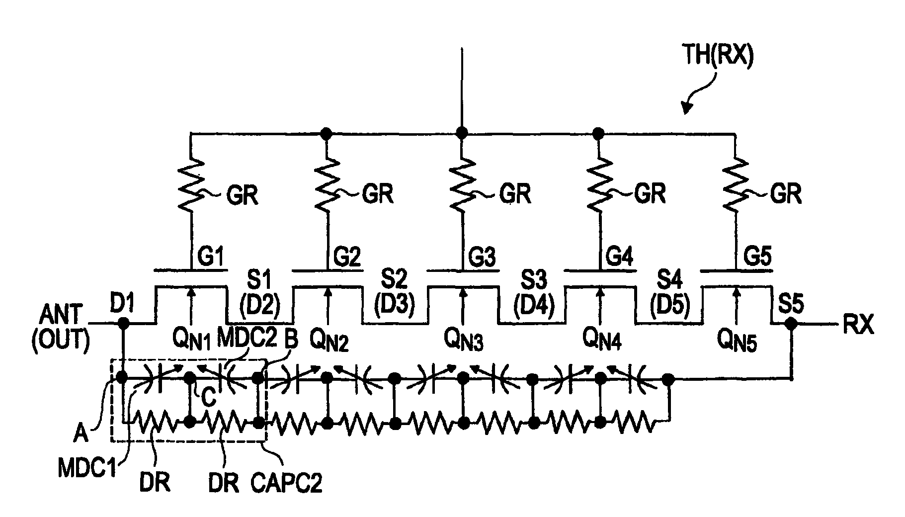
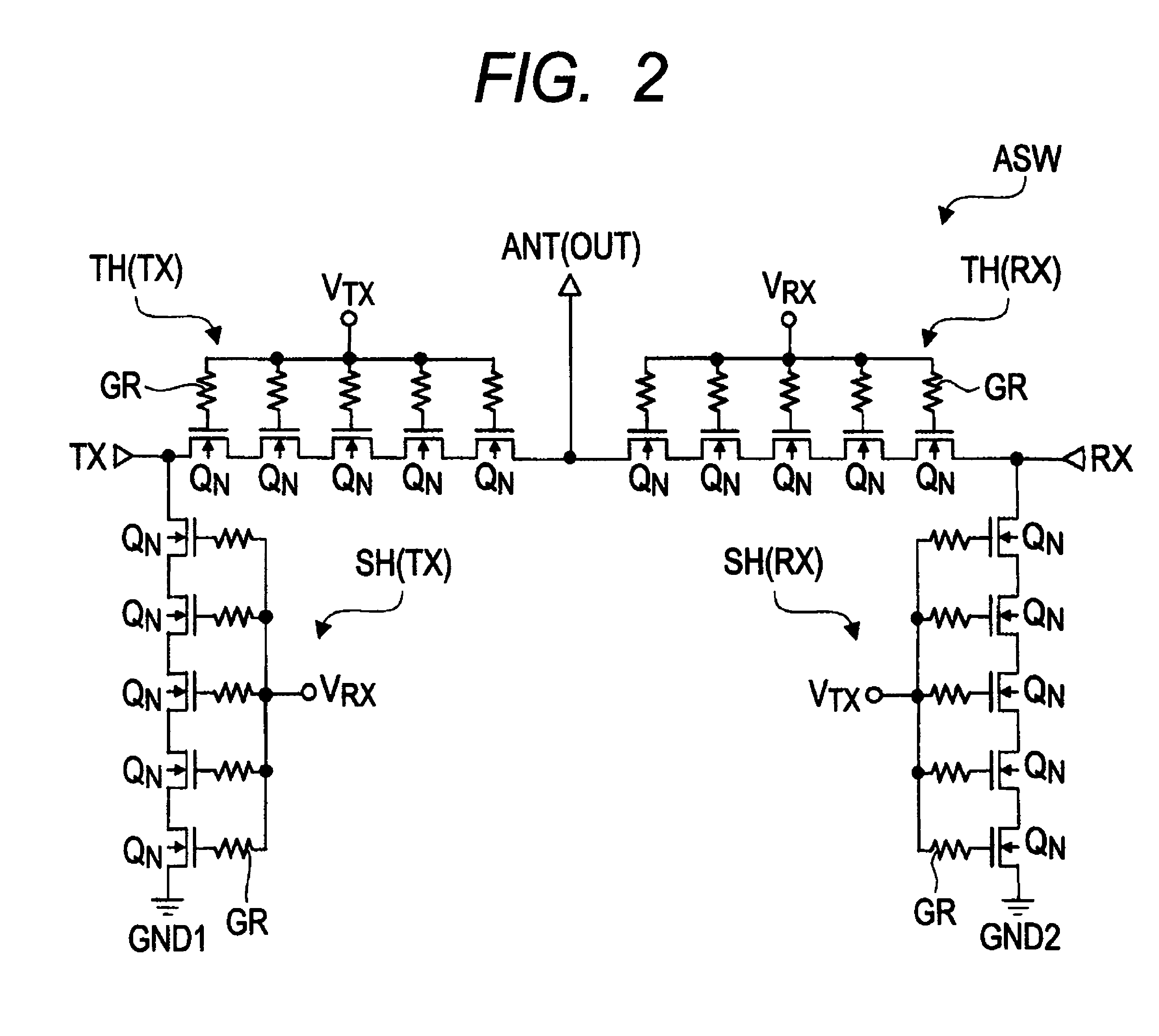
[0224]In the foregoing first embodiment, the description has been given to the example in which, between the respective source regions and the respective drain regions of the plurality of MISFETs QN1 to QN5 included in the RX through transistor TH(RX), the distortion compensating capacitance circuits CAPC2 are provided. In the present second embodiment, a description will be given to a configuration in which the plurality of distortion compensating capacitance circuit CAPC2 are coupled in series between the antenna terminal ANT(OUT) provided with the RF through transistor TH(RX) and the reception terminal RX.
[0225]FIG. 21 is a circuit diagram showing a circuit configuration of the RX through transistor TH(RX) provided with the distortion compensating capacitance circuits CAPC2 in the present second embodiment. As shown in FIG. 21, between the antenna terminal ANT(OUT) and the reception t...
third embodiment
[0241]In the distortion compensating capacitance circuit CAPC2 in the first embodiment, the MOS diode capacitance elements MDC1 and MDC2 are coupled in anti-series so as to electrically couple the electrode EL1 of the MOS diode capacitance element MDC1 to the electrode EL2 of the MOS diode capacitance element MDC2. By contrast, in the present third embodiment, a description will be given to a distortion compensating capacitance circuit in which the MOS diode capacitance elements MDC1 and MDC2 are coupled in anti-series so as to electrically couple the semiconductor region NR1B of the MOS diode capacitance element MDC1 to the semiconductor region NR2B of the MOS diode capacitance element MDC2.
[0242](Distortion Compensating Capacitance Circuit in Third Embodiment)
[0243]FIG. 23(a) is a view showing a structure of a distortion compensating capacitance circuit CAPC3 in the present third embodiment. As shown in FIG. 23(a), the distortion compensating capacitance circuit CAPC3 in the prese...
PUM
 Abstract
Description
Claims
Application Information
 - R&D
- Intellectual Property
- Life Sciences
- Materials
- Tech Scout
- Unparalleled Data Quality
- Higher Quality Content
- 60% Fewer Hallucinations
Browse by: Latest US Patents, China's latest patents, Technical Efficacy Thesaurus, Application Domain, Technology Topic, Popular Technical Reports.
© 2025 PatSnap. All rights reserved.Legal|Privacy policy|Modern Slavery Act Transparency Statement|Sitemap|About US| Contact US: help@patsnap.com


