Leakage resistance detection device for an on-board high voltage device and leakage resistance detection method therefor
a leakage resistance detection and high voltage technology, applied in the direction of electric devices, testing circuits, instruments, etc., can solve the problems of deteriorating detection accuracy of monitoring voltage, inability to make ground abnormality determination immediately, and inability to make detection of ground abnormality in pulse generation period, etc., to achieve the effect of rapid output of resistance abnormality determination and improved search performan
- Summary
- Abstract
- Description
- Claims
- Application Information
AI Technical Summary
Benefits of technology
Problems solved by technology
Method used
Image
Examples
first embodiment
[0061
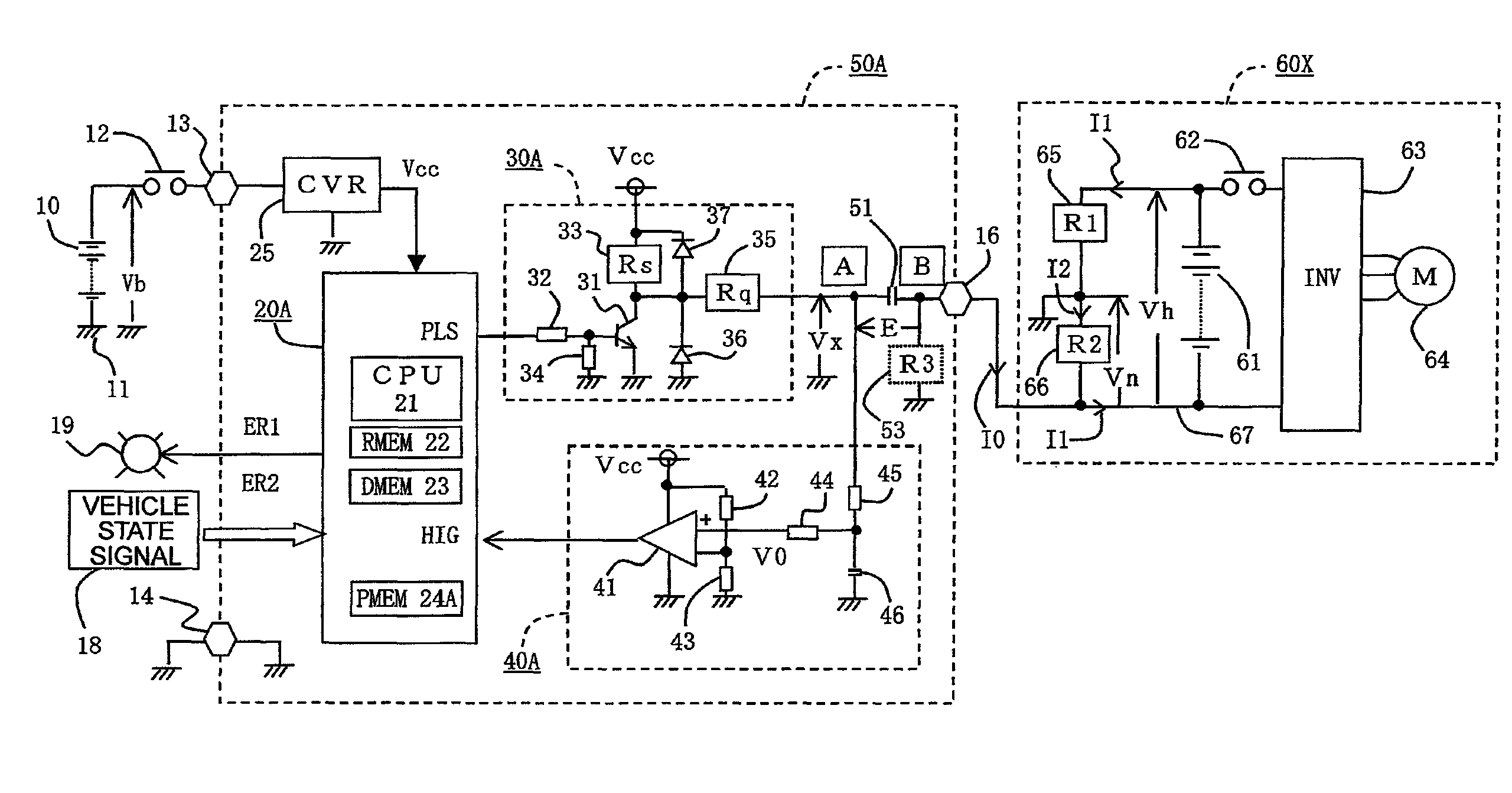
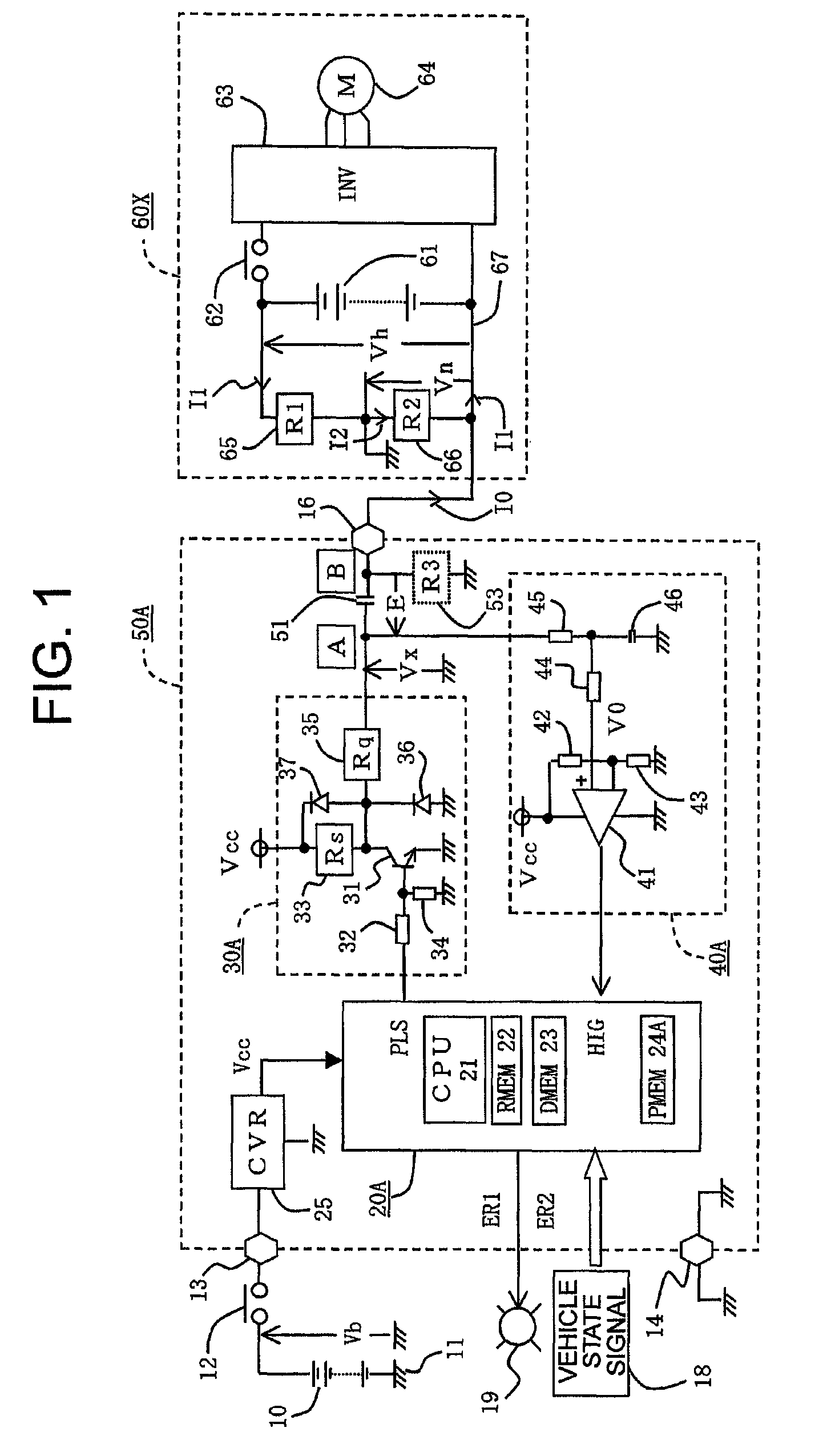
[0062]Now, a description is given with reference to an overall configuration diagram of FIG. 1 illustrating a device according to a first embodiment of the present invention. In FIG. 1, a low voltage DC power source 10, which is externally connected to a leakage resistance detection device 50A, is an on-board battery such as a 12-V secondary lead battery. The low voltage DC power source 10 has a negative terminal grounded to a vehicle body 11. A positive terminal thereof supplies a first power supply voltage Vb via a low voltage power supply switch 12 to a positive-side low voltage power supply terminal 13 provided to the leakage resistance detection device 50A. The low voltage power supply switch 12 uses an output contact of an electromagnetic relay which is energized when a manual power supply switch (not shown) is closed. When the manual power supply switch is opened, the low voltage power supply switch 12 is opened after a short delay time so as to perform delayed feeding.
[...
second embodiment
[0188
[0189]Referring to FIG. 8 which is an overall configuration diagram of a device according to a second embodiment of the present invention, the differences from FIG. 1 are mainly described below. In the drawings, the same reference symbols denote the same or equivalent parts. In FIG. 8, a leakage resistance detection device 50B includes an arithmetic control circuit 20B, a repetitive signal output circuit 30B, and a monitoring signal processing circuit 40B, and detects a leakage resistance of an on-board high voltage device 60Y.
[0190]The first main difference is that, in the on-board high voltage device 60Y, a positive-side power supply line 68 is connected to one terminal B of the coupling capacitor 51 via the interconnection terminal 16, and the positive-side equivalent leakage resistor 65 has an equivalent leakage resistance R2 on the interconnection side while the negative-side equivalent leakage resistor 66 has an equivalent leakage resistance R1 on the non-interconnection ...
third embodiment
[0259
[0260]Referring to FIG. 12 which is an overall configuration diagram of a device according to a third embodiment of the present invention, the differences from FIG. 1 are mainly described below. In the drawings, the same reference symbols denote the same or equivalent parts. In FIG. 12, a leakage resistance detection device 50C includes an arithmetic control circuit 20C, a repetitive signal output circuit 30C, and a monitoring signal processing circuit 40C, and detects a leakage resistance of an on-board high voltage device 60X.
[0261]The first main difference is that the repetitive signal output circuit 30C includes a charge / discharge switching element 31 such as a PNP transistor, and when the output logic level of the repetitive command signal PLS is “H”, an auxiliary switching element 31a becomes conductive via an auxiliary drive resistor 32a so that the charge / discharge switching element 31 becomes conductive via the drive resistor 32, and when the output logic level of the ...
PUM
 Abstract
Description
Claims
Application Information
 - R&D
- Intellectual Property
- Life Sciences
- Materials
- Tech Scout
- Unparalleled Data Quality
- Higher Quality Content
- 60% Fewer Hallucinations
Browse by: Latest US Patents, China's latest patents, Technical Efficacy Thesaurus, Application Domain, Technology Topic, Popular Technical Reports.
© 2025 PatSnap. All rights reserved.Legal|Privacy policy|Modern Slavery Act Transparency Statement|Sitemap|About US| Contact US: help@patsnap.com


