Eureka AIR delivers breakthrough ideas for toughest innovation challenges, trusted by R&D personnel around the world.

Lithium iron phosphate of olivine crystal structure and lithium secondary battery using the same

a technology of olivine crystal structure and lithium secondary battery, which is applied in the direction of cell components, final product manufacturing, sustainable manufacturing/processing, etc., can solve the problems of low stability and high cost, limitations of mass-use as a power source for electric automobiles, and unsuitable for mass-production practical application

Active Publication Date: 2014-12-09
LG ENERGY SOLUTION LTD
View PDF16 Cites 0 Cited by
  • Summary
  • Abstract
  • Description
  • Claims
  • Application Information

AI Technical Summary

Benefits of technology

[0015]A small amount of carbon is released from the olivine-type lithium iron phosphate according to the present invention, when dispersed in water, since carbon (C) is coated on the particle surface of the lithium iron phosphate through uniform and strong bonding force. Accordingly, the lithium iron phosphate can exhibit high electrical conductivity in spite of coating of a small amount of carbon and prevent separation of electrodes in the manufacturing process thereof due to carbon coating with a strong bonding force, thus contributing to improvement in electrode density.
[0031]On the other hand, according to the present invention, remaining sulfur (S) may be used in combination with carbon coating, for example, after a predetermined amount of sulfur is left in lithium iron phosphate by decreasing the repetition number of washing process or washing intensity, carbon coating is performed. For this reason, uniform and strong coating as well as reduction of preparation costs of active material caused by simplification of washing process can be advantageously realized. In particular, when primary particles of lithium iron phosphate are nanomaterials, the overall efficiency of the fabrication process of secondary batteries can be further improved by minimizing the washing process as described above.
[0060]The dying and preparation of the secondary particles may be carried out at the same time by various methods known in the art, including spray drying, fluidized-bed drying, vibration drying, etc. In particular, rotating spray drying is preferred, because it enables preparation of secondary particles in the form of spheres and thus improves tap density.
[0078]The cathode current collector is generally fabricated to have a thickness of 3 to 500 μm. There is no particular limit as to the cathode current collector, so long as it has suitable conductivity without causing adverse chemical changes in the fabricated battery. Examples of the cathode current collector include stainless steel, aluminum, nickel, titanium, sintered carbon, and aluminum or stainless steel which has been surface-treated with carbon, nickel, titanium or silver. If necessary, these current collectors may also be processed to form fine irregularities on the surface thereof so as to enhance adhesive strength to the cathode active materials. In addition, the current collectors may be used in various forms including films, sheets, foils, nets, porous structures, foams and non-woven fabrics.

Problems solved by technology

LiCoO2 is currently used owing to superior physical properties such as cycle life, but has disadvantages of low stability and high-cost due to use of cobalt, which suffers from natural resource limitations, and limitations of mass-use as a power source for electric automobiles.
LiNiO2 is unsuitable for practical application to mass-production at a reasonable cost due to many features associated with preparation methods thereof Lithium manganese oxides such as LiMnO2 and LiMn2O4 have a disadvantage of short cycle life.
However, LiFePO4 disadvantageously causes an increase in internal resistance of batteries due to low electrical conductivity, when used as a cathode active material.
For this reason, when battery circuits are closed, polarization potential increases, thus decreasing battery capacity.
Lithium sources and carbon sources added to improve conductivity disadvantageously generate a great amount of Li2CO3.
Such Li2CO3 is degraded during charging, or reacts with an electrolyte solution to produce CO2 gas, thus disadvantageously causing production of a great amount of gas during storage or cycles.
As a result, disadvantageously, swelling of batteries is generated and high-temperature stability is deteriorated.
The deterioration in overall physical properties is inevitable during design of batteries and further, a great amount of carbon used for coating is present in the form of aggregates between particles, thus disadvantageously making it difficult to realize uniform coating.

Method used


Image

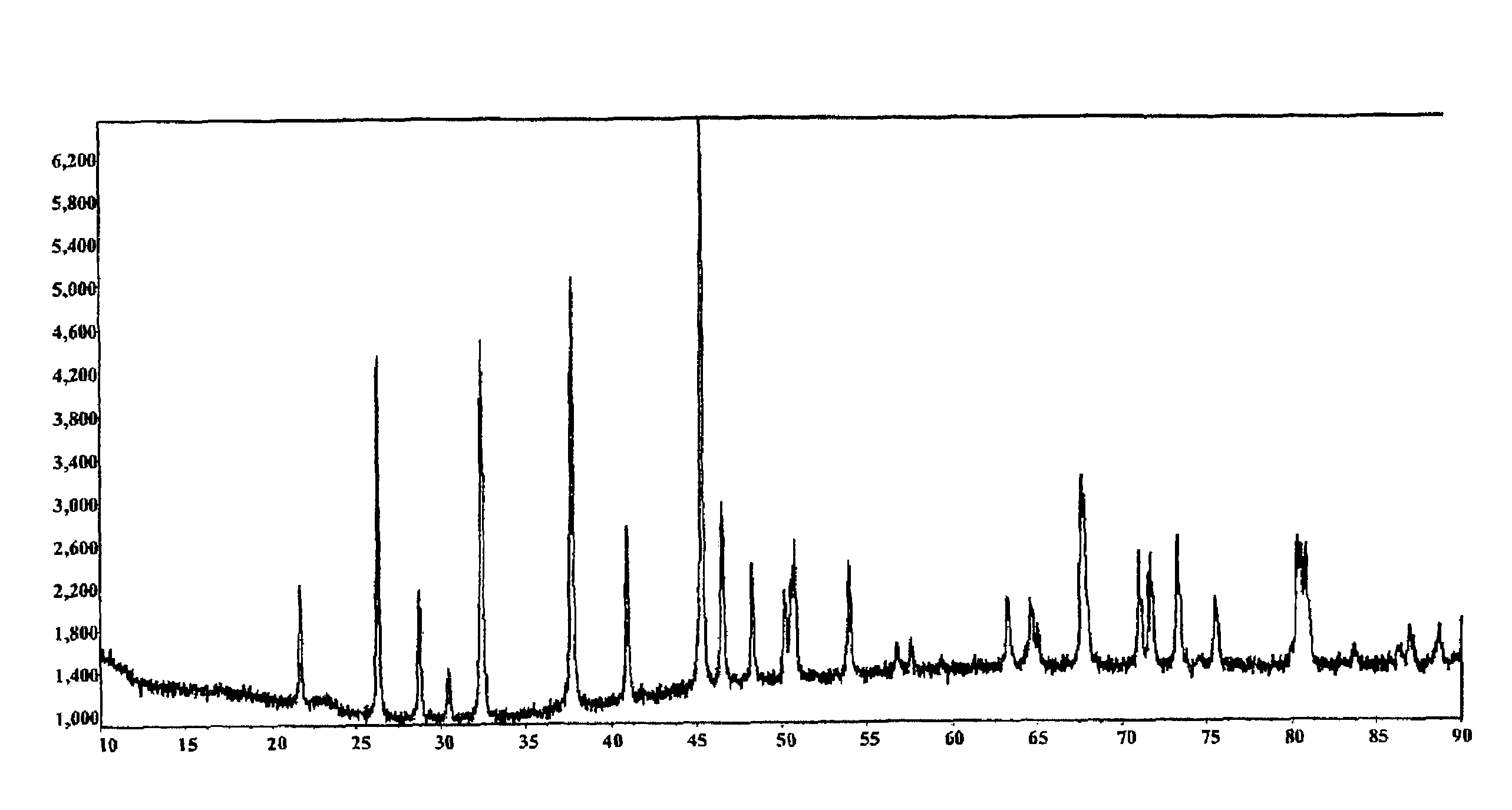
  • Lithium iron phosphate of olivine crystal structure and lithium secondary battery using the same
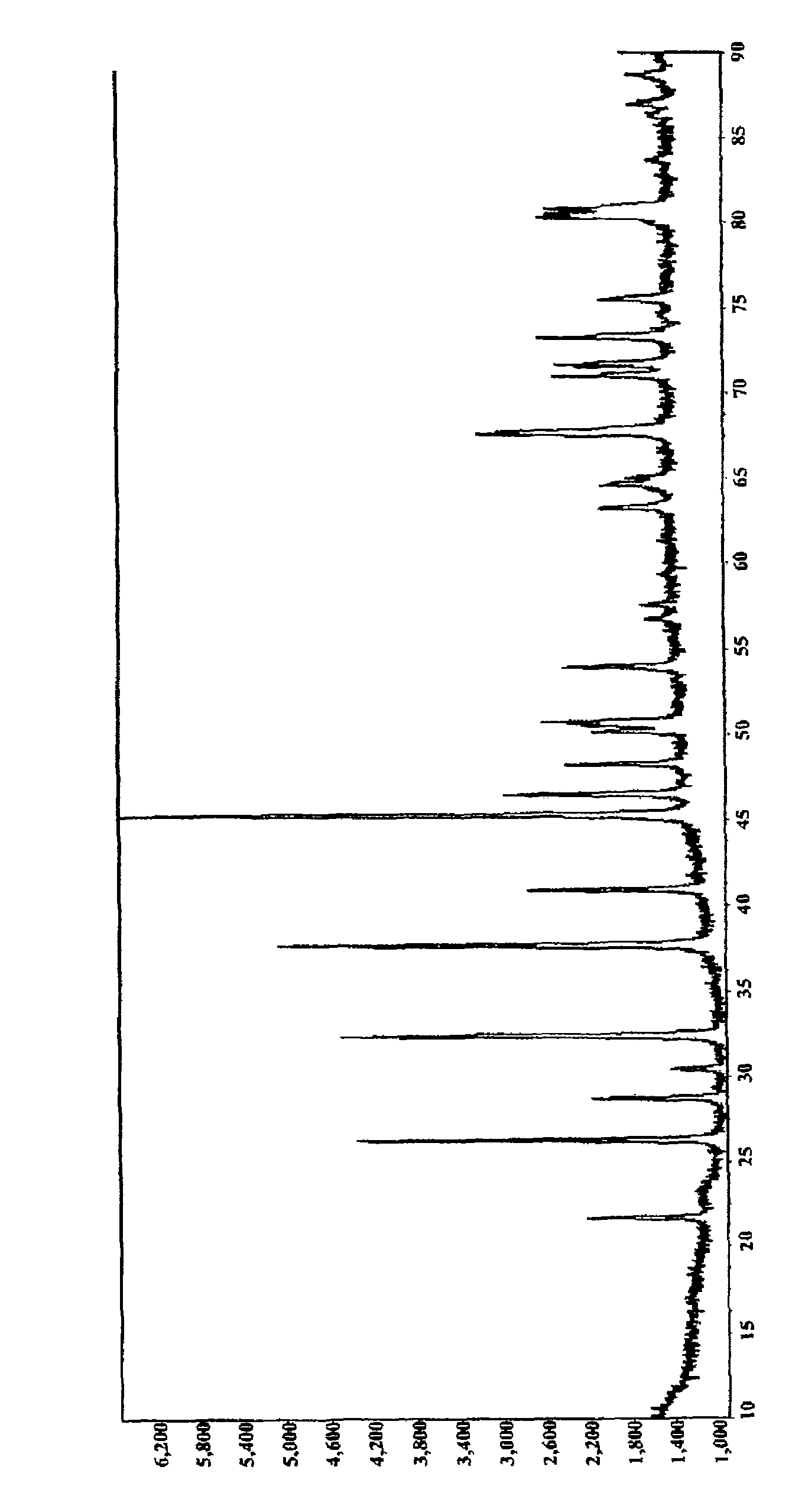
  • Lithium iron phosphate of olivine crystal structure and lithium secondary battery using the same

Examples


example 2

[0098]21.5 g of LiOH—H2O, 27 g of aqueous ammonia (˜29 wt %), and 950.5 g of distilled water were mixed with one another and dissolved to prepare an aqueous solution A. In the same manner as above, 72.65 g of FeSO4-7H2O, 6.065 g of sucrose, 28.85 g of phosphoric acid (85 wt %), and 890.435 g of distilled water were mixed with one another and dissolved to prepare an aqueous solution B.

[0099]Supercritical water (430° C., 240 bar) was flowed at an elevated temperature and at an elevated pressure at 100 g / min into a continuous tubular reactor, and the aqueous solution A and the aqueous solution B were flowed at a flow rate of 15 g / min and brought in contact with the supercritical water for several seconds and mixed to induce reaction.

[0100]The resulting product was cooled and filtered at the end of the tubular reactor to obtain a slurry containing an intermediate. A controlled concentration of water was added to the slurry to obtain a slurry having a solid content of 20 wt %, and 7 wt %...

example 3

[0101]40.9 g of LiOH—H2O, 32.4 g of aqueous ammonia (˜29 wt %), and 934.7 g of distilled water were mixed with one another and dissolved to prepare an aqueous solution A. In the same manner as above, 140.3 g of FeSO4-7H2O, 13.13 g of sucrose, 57.7 g of phosphoric acid (85 wt %), 3.1 g of sulfur and 767 g of distilled water were mixed with one another and dissolved to prepare an aqueous solution B. Supercritical water (450° C., 250 bar) was flowed at an elevated temperature and at an elevated pressure at 100 g / min into a continuous tubular reactor, and the aqueous solution A and the aqueous solution B were flowed at a flow rate of 15 g / m in and brought in contact with the supercritical water for several seconds and mixed to induce reaction. At this time, the aqueous solution A first contacted the aqueous solution B to produce a slurry and was then reacted with the supercritical water. The aqueous solution A was reacted with supercritical water as soon as possible after production of ...

example 4

[0105]34.8 g of LiOH—H2O, 37.1 g of aqueous ammonia (˜29 wt %), and 904.7 g of distilled water were mixed with one another and dissolved to prepare an aqueous solution A. In the same manner as above, 104.2 g of FeSO4-7H2O, 14.13 g of sucrose, 57.7 g of phosphoric acid (85 wt %), 15.3 g of NiSO4-7H2O and 795.7 g of distilled water were mixed with one another and dissolved to prepare an aqueous solution B. Supercritical water (455° C., 240 bar) was flowed at an elevated temperature and at an elevated pressure at 100 g / min into a continuous tubular reactor, and the aqueous solution A and the aqueous solution B were flowed at a flow rate of 15 g / min and brought in contact with the supercritical water for several seconds and mixed to induce reaction. At this time, the aqueous solution A first contacted the aqueous solution B to produce a slurry and was then reacted with the supercritical water. The aqueous solution A was reacted with supercritical water as soon as possible after producti...


PUM

PropertyMeasurementUnit
thicknessaaaaaaaaaa
volume densityaaaaaaaaaa
thicknessaaaaaaaaaa

Abstract

Disclosed is lithium iron phosphate having an olivine crystal structure wherein carbon (C) is coated on particle surfaces of the lithium iron phosphate, wherein, when a powder of the lithium iron phosphate is dispersed in water, water is removed from the resulting dispersion and the resulting lithium iron phosphate residue is quantitatively analyzed, a ratio of the carbon-released lithium iron phosphate with respect to the total weight of the carbon-coated lithium iron phosphate is 0.005% by weight or less. Advantageously, the olivine-type lithium iron phosphate is not readily separated through uniform thin film coating on the surface of the lithium iron phosphate and exhibits superior conductivity and density, since carbon is coated on particle surfaces of lithium iron phosphate in a state in which the amount of carbon released in water is considerably small.

Description

TECHNICAL FIELD[0001]The present invention relates to lithium iron phosphate having an olivine crystal structure wherein carbon (C) is coated on particle surfaces of the lithium iron phosphate, wherein, when a powder of the lithium iron phosphate is dispersed in water, water is removed from the resulting dispersion and the resulting lithium iron phosphate residue is quantitatively analyzed, a ratio of the carbon-released lithium iron phosphate with respect to the total weight of the carbon-coated lithium iron phosphate is 0.005% by weight or less.BACKGROUND ART[0002]Technological development and increased demand for mobile equipment have led to a rapid increase in the demand for secondary batteries as energy sources. Among these secondary batteries, lithium secondary batteries having high energy density and voltage, long lifespan and low self-discharge are commercially available and widely used.[0003]The lithium secondary batteries generally use a carbon material as an anode active ...

Claims


Application Information

Patent Timeline
Patent Type & Authority Patents(United States)
IPC IPC(8): H01M4/58H01M4/36H01M10/052H01M4/62H01M4/02H01M4/52
CPCH01M4/5825H01M4/625H01M10/052Y02E60/122Y02T10/7011C01B25/45C01P2004/80Y02E60/10H01M4/525H01M4/583H01M10/0525Y02T10/70Y02P70/50
Inventor NOH, HYUN KUKPARK, HONG KYUPARK, SU-MINLEE, JI EUNPARK, CHEOL-HEE
Owner LG ENERGY SOLUTION LTD
Why Eureka
Eureka Blog
Learn More