Exhaust particulate management for gasoline-fueled engines

a technology for exhaust particulate management and gasoline-fueled engines, which is applied in the direction of machines/engines, separation processes, mechanical equipment, etc., to achieve the effect of less catalys

Inactive Publication Date: 2015-01-06
GM GLOBAL TECH OPERATIONS LLC
View PDF27 Cites 1 Cited by
  • Summary
  • Abstract
  • Description
  • Claims
  • Application Information

AI Technical Summary

Benefits of technology

[0011]In some embodiments, it may also be preferred to locate the particulate matter filter immediately downstream of a platinum group metal-coated or a three way catalyst-coated monolith which will also purify the exhaust and heat the exhaust gas to consume trapped particulate matter in the thin, particulate matter filter layer. The placement of a catalyst-coated monolith close to the exhaust outlet of the engine may enable the use of a smaller monolith using less catalyst.
[0013]Thus, a gasoline particulate matter filter is provided that functions in a very hot exhaust gas location. It is preferred that the filter substrate (such as a wall-flow filter) be located within about two to about eighty centimeters of the exhaust manifold of the engine. A thin layer of fine pore, high porosity, high temperature resistant filter material, carried on a durable ceramic, flow-through substrate, removes particulate, carbon-containing material from the exhaust. In contrast to the treatment of diesel exhaust, this filter material is relied on to remove particulate matter from the exhaust stream because the accumulating soot is regularly being passively oxidized. The filtered exhaust gas exits the filter after flowing through the relatively large pore ceramic body. Other elements of the exhaust system for oxidation and / or reduction of gaseous contaminants are complemented and not adversely affected by the trap for particulate matter. This invention greatly reduces the frequency or likelihood of active soot regeneration that requires diversion of engine fuel to burn and remove the filtered particulate matter.

Problems solved by technology

However, unlike the management of diesel engine particulate material, the soot layer is not utilized, or relied on, as a filter medium; the filtered particulate material is passively oxidized from the filter layer by suitably hot, oxygen-containing exhaust gas flowing through it during engine operation.

Method used


Image

  • Exhaust particulate management for gasoline-fueled engines
  • Exhaust particulate management for gasoline-fueled engines
  • Exhaust particulate management for gasoline-fueled engines

Examples


Embodiment Construction

[0018]Vehicle drivers have long observed a cloud of black, agglomerated particulates that may emanate from unfiltered / untreated exhaust of a diesel engine powered vehicle, particularly when the vehicle is accelerating under heavy engine loading. Such a cloud of particulates is not observed in the exhaust of gasoline-fueled engines. Still gasoline engines produce some very small, generally spherical, carbonaceous particles (e.g., about 20 to about 200 nanometers in size. It is recognized that the total mass of such particles from a mid-size vehicle engine may exceed about five milligrams per kilometer of driving and about 1012 particles per kilometer. A purpose of this invention is to reduce the amount of such very small particles from the gasoline engine exhaust without adversely affecting the fuel efficiency of the engine and the present successful reduction of undesirable gaseous constituents in the exhaust.

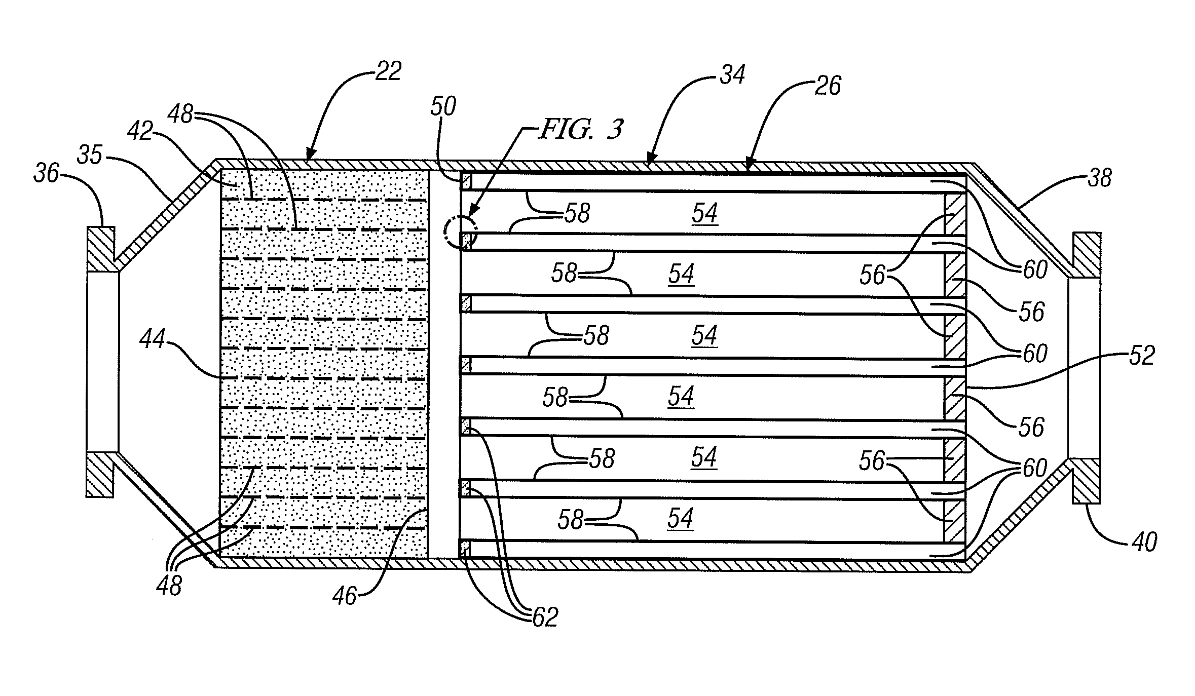
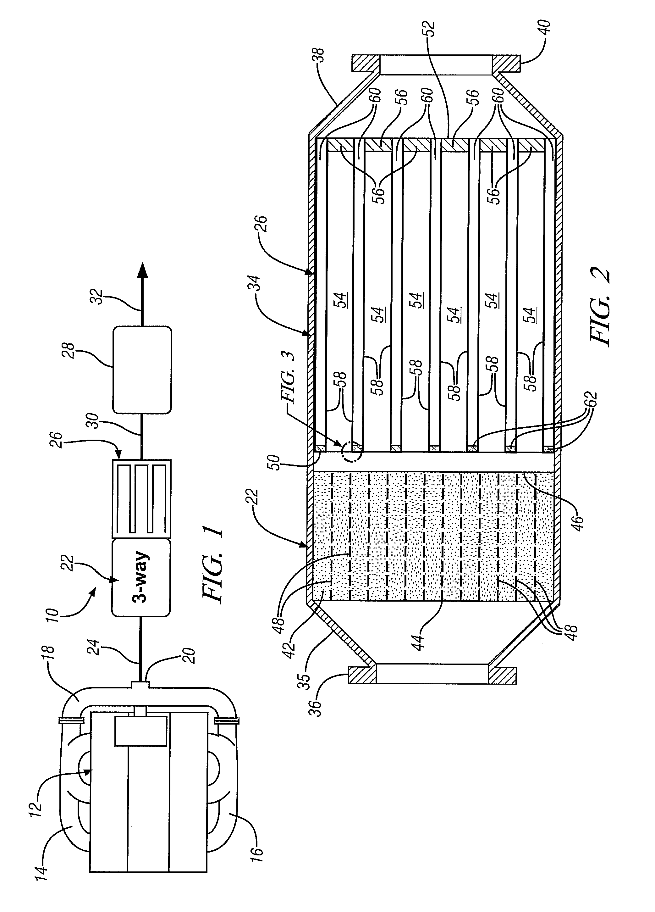
[0019]FIG. 1 is a schematic illustration of one embodiment of an exhaust s...


PUM

PropertyMeasurementUnit
thicknessaaaaaaaaaa
thicknessaaaaaaaaaa
porosityaaaaaaaaaa

Abstract

A thin layer of low mean-pore-size filter material that permanently accommodates the accumulation of exhaust particulates (as soot or a soot cake) is carried on a porous ceramic support. The supported filter material is closely coupled with the exhaust manifold of the engine, for the purpose of passive regeneration of stored particulates, and removes particulate matter from the exhaust which is directed through the filter layer and ceramic support. The oxygen content of the exhaust oxidizes the particulate matter on the filter material. In a preferred embodiment, a thin layer of the filter material is supported on inlet channel walls of a wall flow-through ceramic filter body to remove the particles from the exhaust. The filter body comprises an upstream exhaust gas flow inlet face with openings to a plurality of inlet channels and a downstream face with a like plurality of openings from outlet channels. The inlet channels are closed at the downstream face and the outlet channels are closed at the inlet face. So the exhaust stream enters the inlet channels and flows through the filter layers and supporting channel walls to an outlet channel. The filtered exhaust stream exits the outlet end of the filter body and is combined into an exhaust passage downstream of the filter body for further treatment as may be necessary.

Description

TECHNICAL FIELD[0001]This disclosure and invention pertain to the removal and destruction of particulate material (largely carbon) in the exhaust of gasoline-fueled internal combustion engines such as are used on automotive vehicles. More specifically, this invention pertains to the trapping and oxidation of such particles in an exhaust gas flow-through filter placed close to the exhaust manifold of the engine.BACKGROUND OF THE INVENTION[0002]In many modern gasoline-fueled engines, the fuel is injected sequentially and directly into each cylinder of a multi-cylinder engine. There the fuel is mixed with at least a stoichiometric amount of air, spark-ignited, and burned to produce the powered stroke of the piston. Combusted gas is exhausted from each engine cylinder by reciprocating piston action and combined in one or more exhaust manifolds. The exhaust enters an exhaust duct in which it is treated by flowing through one or more catalytic converters before the exhaust is discharged t...

Claims


Application Information

Patent Timeline
Patent Type & Authority Patents(United States)
IPC IPC(8): B01D45/00B01D53/00B01D53/56B01D57/00B01D46/00B01D47/00B01D53/94F01N3/022F01N3/035F01N3/10F01N3/28F01N13/00
CPCF01N3/035B01D53/944F01N3/0222F01N3/101F01N3/103F01N3/2828F01N13/0097B01D2255/915B01D2255/9205B01D2258/014F01N2330/48F01N2340/00F01N2340/02F01N2510/0684Y02T10/22Y02T10/12
Inventor KOCH, CALVIN K.NAJT, PAUL M.NARAYANASWAMY, KUSHALHILDEN, DAVID L.
Owner GM GLOBAL TECH OPERATIONS LLC
Why Eureka
Try Eureka