Methods for preparing carbon black sheet with metallic nanoparticle thin layer by electrophoresis deposition and membrane electrode assembly (MEA) for proton exchange membrane fuel cell

a proton exchange membrane and carbon black sheet technology, applied in cell components, electrochemical generators, coatings, etc., can solve the problems of platinum catalyst among elements constituting mea taking up about 70% of material costs, platinum catalyst may not be selectively formed on a specific site in the catalyst layer, and reduce manufacturing costs significantly. , the effect of enhancing the efficiency of metal catalys

Inactive Publication Date: 2015-01-06
IND COOP FOUND CHONBUK NAT UNIV
View PDF6 Cites 0 Cited by
  • Summary
  • Abstract
  • Description
  • Claims
  • Application Information

AI Technical Summary

Benefits of technology

[0032]Unlike conventional manufacturing methods, a manufacturing method of a carbon black sheet with a thin layer of metal nanoparticles of the present invention allows metal nanoparticles such as platinum, etc. to be uniformly dispersed on a carbon black layer and manufactured into a thin layer, enhancing the efficiency of a metal catalyst such as platinum, etc. and minimizing the amount of the metal used to reduce the manufacturing costs significantly.
[0033]Further, a carbon black sheet with a multi-layer structure or a thin layer of different metal nanoparticles may be manufactured and thus its usage may be maximized.
[0034]In addition, because the present invention employs a pulse electroplating process based on a deposition process using electrophoresis, carbon black sheets may be continuously supplied to the pulse electroplating process to manufacture a carbon black sheet with a metal nanoparticle thin layer by a continuous process, leading to easy manufacturing of a large carbon black sheet electrode and its mass production to contribute greatly to the commercialization of fuel cells.

Problems solved by technology

This MEA takes up about 70% of a material cost of a polymer electrolyte membrane fuel cell stack and is the biggest obstacle to the commercialization of a polymer electrolyte membrane fuel cell.
In addition, the platinum catalyst among elements constituting the MEA takes up the highest portion of the price.
However, a platinum layer may not be selectively formed on a specific site in the catalyst layer by a spray method or a decal method, which is a conventional method of forming a platinum nanoparticles catalyst layer.
Due to these problems, a platinum catalyst layer was applied thicker than necessary, and as a result, this has been responsible for the inability to reduce the amount of a platinum catalyst used.

Method used


Image

  • Methods for preparing carbon black sheet with metallic nanoparticle thin layer by electrophoresis deposition and membrane electrode assembly (MEA) for proton exchange membrane fuel cell
  • Methods for preparing carbon black sheet with metallic nanoparticle thin layer by electrophoresis deposition and membrane electrode assembly (MEA) for proton exchange membrane fuel cell
  • Methods for preparing carbon black sheet with metallic nanoparticle thin layer by electrophoresis deposition and membrane electrode assembly (MEA) for proton exchange membrane fuel cell

Examples


example 2

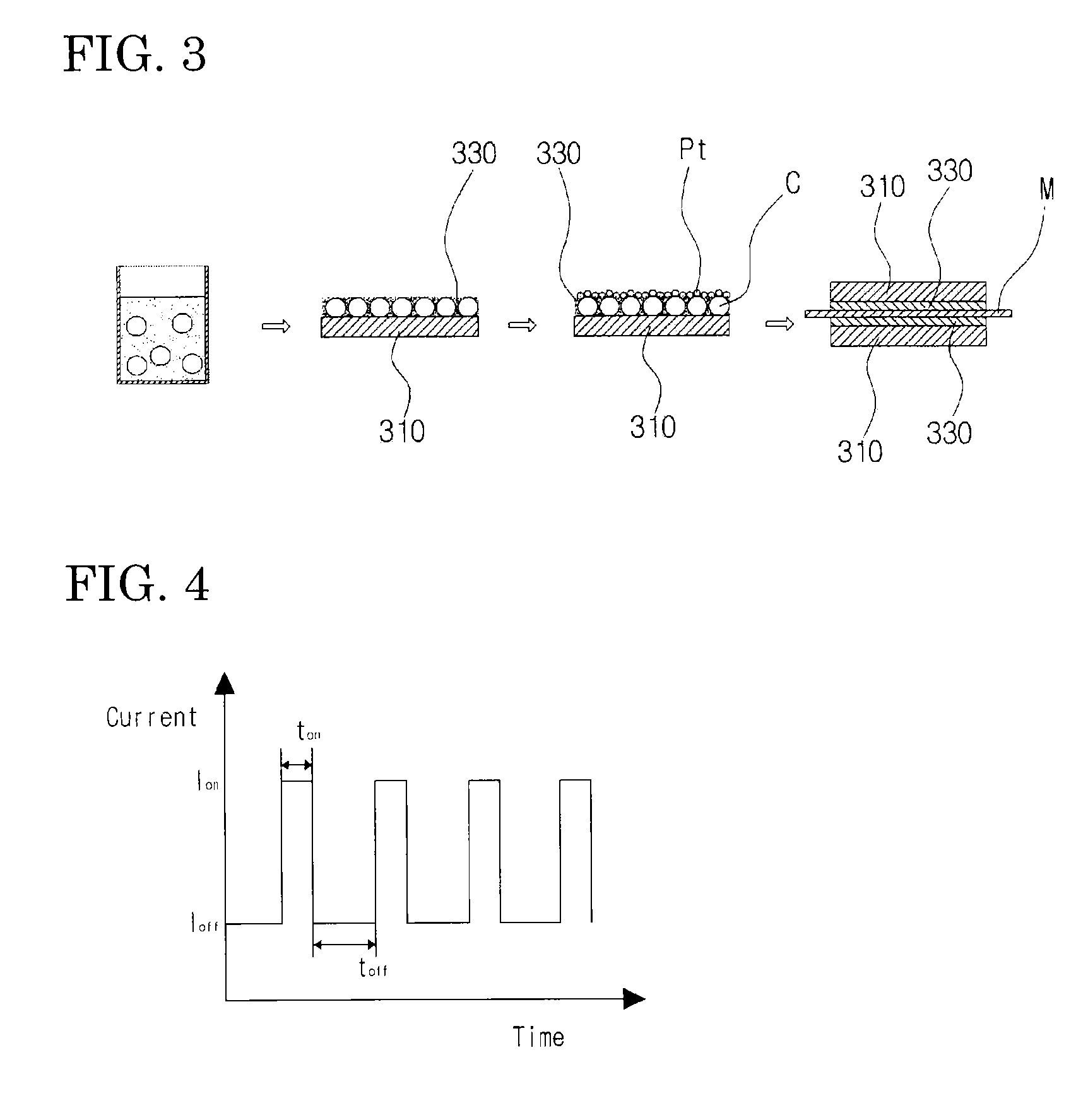
[0061]Unlike in Example 1, a carbon black sheet with a thin layer of platinum nanoparticles was manufactured by maintaining the pH of the platinum nanoparticle suspension electrolyte at 2 and changing the dwell time ton from 0.15 sec to 0.75 sec. FE-SEM images of carbon black sheets with a thin layer of platinum nanoparticles manufactured are shown in FIGS. 12 to 15. As shown in FIGS. 12 to 15, it was confirmed that platinum nanoparticles were deposited on the carbon black layer under all the dwell time conditions, and the amount of platinum nanoparticles deposited could be controlled by controlling the dwell time.

example 3

[0067]Unlike in Example 1, a gold (Au) nanoparticle suspension electrolyte was used to prepare a carbon black sheet with a thin layer of gold nanoparticles instead of the platinum nanoparticle suspension electrolyte.

[0068]In this case, HAuCl44H2O and sodium citrate were used as a starting material for synthesis of a gold nanoparticle colloid and a reducing agent, respectively. In order to synthesize the gold nanoparticle colloid, 1% of HAuCl44H2O was first prepared, 1 ml of the reagent was diluted in 499 ml of H2O, the resulting aqueous solution was vigorously stirred while being heated to about 99° C., and then 28 ml of 1% sodium citrate was added for preparation. The gold colloid synthesized had an average diameter of 15 nm.

[0069]A mixed solution of 1 M H2SO4 and 1 M CH3OH was used as an electrolyte solution, and 50 ml of a gold nanoparticle colloid solution was mixed with 200 ml of the electrolyte solution to prepare a gold (Au) nanoparticle suspension electrolyte. Gold nanoparti...

example 4

[0071]A carbon black sheet with a thin layer of gold nanoparticles was manufactured in the same manner as in Example 3, then a complex deposition of platinum nanoparticles was performed on a gold nanoparticle-supported carbon black by maintaining Ion and Ioff at 30 mA / cm2 and 0 mA / cm2, respectively, as in Example 1, setting ton at 0.25 sec, and adjusting the pH of an electrolyte in which platinum nanoparticles were suspended to 2, and the FE-SEM image is shown in FIG. 19.

[0072]It is confirmed from the SEM image in FIG. 19 that platinum nanoparticles were deposited simultaneously on the carbon black layer and on gold nanoparticles on the carbon black layer, and it is determined that platinum nanoparticles were deposited more on gold nanoparticles with a higher electric conductivity than on the carbon black layer with a lower electric conductivity to form complex nanoparticles. When pulse electroplating and a metal nanoparticle suspension electrolyte are used together, it can be confi...


PUM

PropertyMeasurementUnit
pHaaaaaaaaaa
temperatureaaaaaaaaaa
pHaaaaaaaaaa

Abstract

A carbon black sheet with a thin layer of metal nanoparticles is provided by pulse electroplating, which allows metal nanoparticles such as platinum to be uniformly dispersed on a carbon black layer and is very thin, enhancing the efficiency of a metal catalyst such as platinum. The process is also used to form a polymer membrane electrode assembly (MEA) for a fuel cell.

Description

CROSS-REFERENCE TO RELATED APPLICATION[0001]This application is a co-pending application which claims priority to PCT Application No. PCT / KR2009 / 004037, filed Jul. 21 2009, which claims priority to and the benefit of Korean Patent Application No. 10-2009-0007202, filing date Jan. 30, 2009 both of which are incorporated by reference in their entirety.TECHNICAL FIELD[0002]The present invention relates to a manufacturing method of a carbon black sheet which is very thin by uniformly dispersing metal nanoparticles such as platinum, etc. on a carbon black layer using pulse electroplating, and a membrane electrode assembly (MEA) for a fuel cell by using a carbon black sheet manufactured thereby.BACKGROUND ART[0003]A polymer electrolyte membrane fuel cell largely consists of an end plate, a current collector plate, a bi-polar plate, a gas diffusion layer, a metal nanoparticle catalyst layer, and a polymer electrolyte membrane, and among them, a gas diffusion layer of positive and negative ...

Claims


Application Information

Patent Timeline
Patent Type & Authority Patents(United States)
IPC IPC(8): H01M4/36C25D5/18C25D5/54C25D15/00H01M4/86H01M4/88H01M4/92H01M8/10
CPCC25D5/18C25D5/54C25D15/00H01M4/8605H01M4/8853H01M4/926H01M2008/1095Y02E60/50C25D5/611C25D15/02H01M8/1004
Inventor YU, YEON TAE
Owner IND COOP FOUND CHONBUK NAT UNIV
Why Eureka
Try Eureka