
Silicon nitride powder for siliconnitride phosphor, Sr3Al3Si13O2N21 phosphor and β-sialon phosphor both obtained using same, and processes for producing these

a technology of silicon nitride and silicon nitride, which is applied in the field of silicon nitride powder, can solve the problems of phosphor disclosure, and achieve the effect of high luminan

Inactive Publication Date: 2015-05-05
UBE IND LTD
View PDF21 Cites 4 Cited by
  • Summary
  • Abstract
  • Description
  • Claims
  • Application Information

AI Technical Summary

Benefits of technology

This patent describes the invention of silicon nitride powder that can be used to make phosphors for vacuum fluorescent displays, field emission displays, plasma display panels, cathode ray tubes, and light emitting diodes. The use of this powder can result in higher luminance for the phosphors. This patent also provides processes for producing these phosphors.

Problems solved by technology

The phosphor disclosed in Patent Literature 1 is, however, inappropriate for an application since the optimum excitation wavelength is present in an ultraviolet range.

Method used


Image

  • Silicon nitride powder for siliconnitride phosphor, Sr<sub>3</sub>Al<sub>3</sub>Si<sub>13</sub>O<sub>2</sub>N<sub>21 </sub>phosphor and β-sialon phosphor both obtained using same, and processes for producing these

Examples


example 1

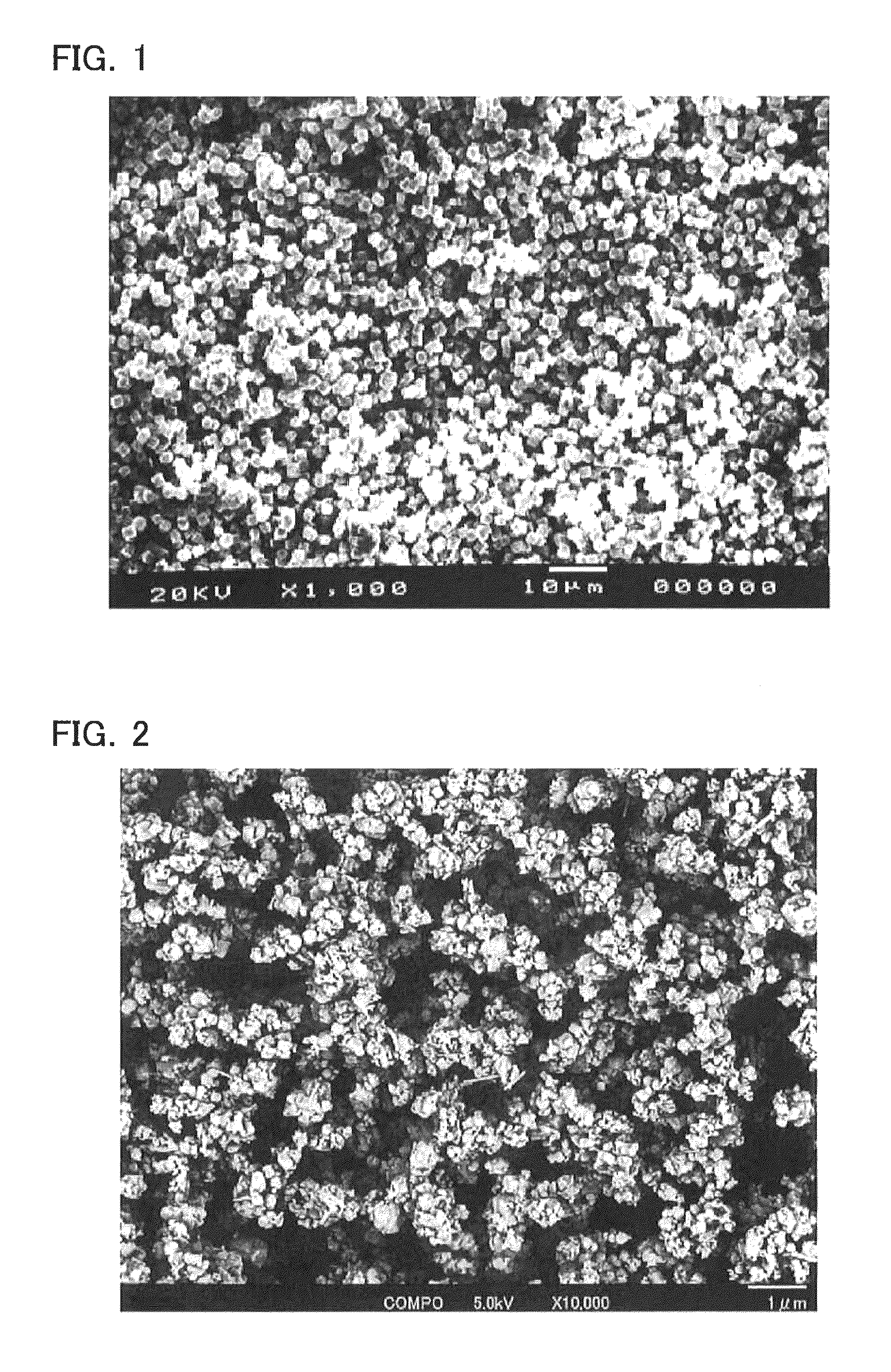
[0052]First, a crystalline silicon nitride powder needed in the invention was produced. The production method was as follows.

[0053]By reacting a toluene solution containing silicon tetrachloride in a concentration of 50% by volume with liquid ammonia, silicon diimide having powder volume density (that is, apparent density) of 0.13 g / cm3 was produced and then subjected to thermal degradation at 1150° C. under nitrogen gas atmosphere to obtain an amorphous silicon nitride powder having powder volume density that is, apparent density) of 0.25 g / cm3. In the resulting material, metal impurities present in the amorphous silicon nitride powder were lowered to 10 ppm or less according to a known method for improving materials of a reaction vessel and friction state between powder and a metal in an apparatus or handling the powder. Further, nitrogen gas with the oxygen concentration of 0.5% by volume was purged into the heating furnace.

[0054]The amorphous silicon nitride powder was filled in...

example 2

[0057]The nitrogen gas purged into the heating furnace for obtaining an amorphous silicon nitride powder by heating silicon diimide was introduced while the oxygen content in the nitrogen gas was controlled to 0.0006% by volume or less. Other than that, the crystalline silicon nitride powder according to Example 2 was produced in the same manner as Example 1. The specific surface area of the obtained amorphous silicon, nitride was 1.0 m2 / g, the average particle diameter was 3.0 μm, and the oxygen content was 0.34% by weight.

example 3

[0058]The nitrogen gas purged into the heating furnace for obtaining an amorphous silicon nitride powder by heating silicon diimide was introduced while the oxygen content in the nitrogen gas was controlled to 0.6% by volume. In addition, the temperature for calcining the amorphous silicon nitride was slowly increased from 1100 to 1400° C. in 10° C. / h. Other than that, the crystalline silicon nitride powder according to Example 3 was produced in the same manner as Example 1. The specific surface area of the obtained amorphous silicon nitride was 0.3 m2 / g, the average particle diameter was 8.0 μm, and the oxygen content was 0.75% by weight.


PUM

PropertyMeasurementUnit
specific surface areaaaaaaaaaaa
average particle diameteraaaaaaaaaa
specific surface areaaaaaaaaaaa

Abstract

Provided is a silicon nitride powder for siliconitride phosphor having high luminance, a Sr3Al3Si13O2N21 phosphor and a β-Sialon phosphor using the powder, which can be used for vacuum fluorescent displays (VFDs), field emission displays (FEDs), plasma display panels (PDPs), cathode ray tubes (CRTs), light emitting diodes (LEDs), or the like, and processes for producing these phosphors. The silicon nitride powder for the siliconitride phosphors is a crystalline silicon nitride powder for use as a raw material for producing siliconitride phosphors including a silicon element, a nitrogen element, and an oxygen element, and has an average particle diameter of 1.0 to 12 μm and an oxygen content of 0.2 to 0.9% by weight.

Description

RELATED / PRIORITY APPLICATION[0001]This application is a National Phase filing regarding International Application No. PCT / JP2011 / 067509, filed on Jul. 29, 2011, which relies upon Japanese Application No. JP2010-184041, filed on Aug. 19, 2010, and Japanese Patent Application No. 2010-188649, filed on Aug. 25, 2010, for priority.TECHNICAL FIELD[0002]The present invention relates to a Sr3Al3Si13O2N21 phosphor, and a β-Sialon phosphor having β-type Si3N4 crystal structure, in which the phosphors have improved fluorescent intensity, and are used for displays, a back light for liquid crystal, a fluorescent lamp, a white-light emitting diode, or the like, a method for producing them, and a silicon nitride powder for siliconitride phosphors which is used as a raw material for them.BACKGROUND ART[0003]Recently, a white-light emitting diode having near ultraviolet to blue-light emitting diode as an excitation source is actively studied. As a green phosphor, a β-Sialon phosphor activated by a ...

Claims


Application Information

Patent Timeline
Patent Type & Authority Patents(United States)
IPC IPC(8): C09K11/08C09K11/77C01B21/068C01B21/082
CPCC09K11/0838C01B21/068C01B21/0826C09K11/7734Y10T428/2982C01P2002/54C01P2004/03C01P2004/52C01P2004/61C01P2006/12C01P2006/80C09K11/77348
Inventor FUJINAGA, MASATAKASAKAI, TAKUMAJIDA, SHINSUKE
Owner UBE IND LTD
Learn More