
Process of making a three-dimensional structure on a support structure

a three-dimensional structure and support structure technology, applied in electrographic process, instruments, transportation and packaging, etc., can solve the problems of increasing the requirements of transplantation, insufficient control of resolution, and high complexity of specific manufacture of transplantation, so as to avoid thermal stress on the printer itself.

Inactive Publication Date: 2015-08-04
FRAUNHOFER GESELLSCHAFT ZUR FOERDERUNG DER ANGEWANDTEN FORSCHUNG EV +1
View PDF19 Cites 5 Cited by
  • Summary
  • Abstract
  • Description
  • Claims
  • Application Information

AI Technical Summary

Benefits of technology

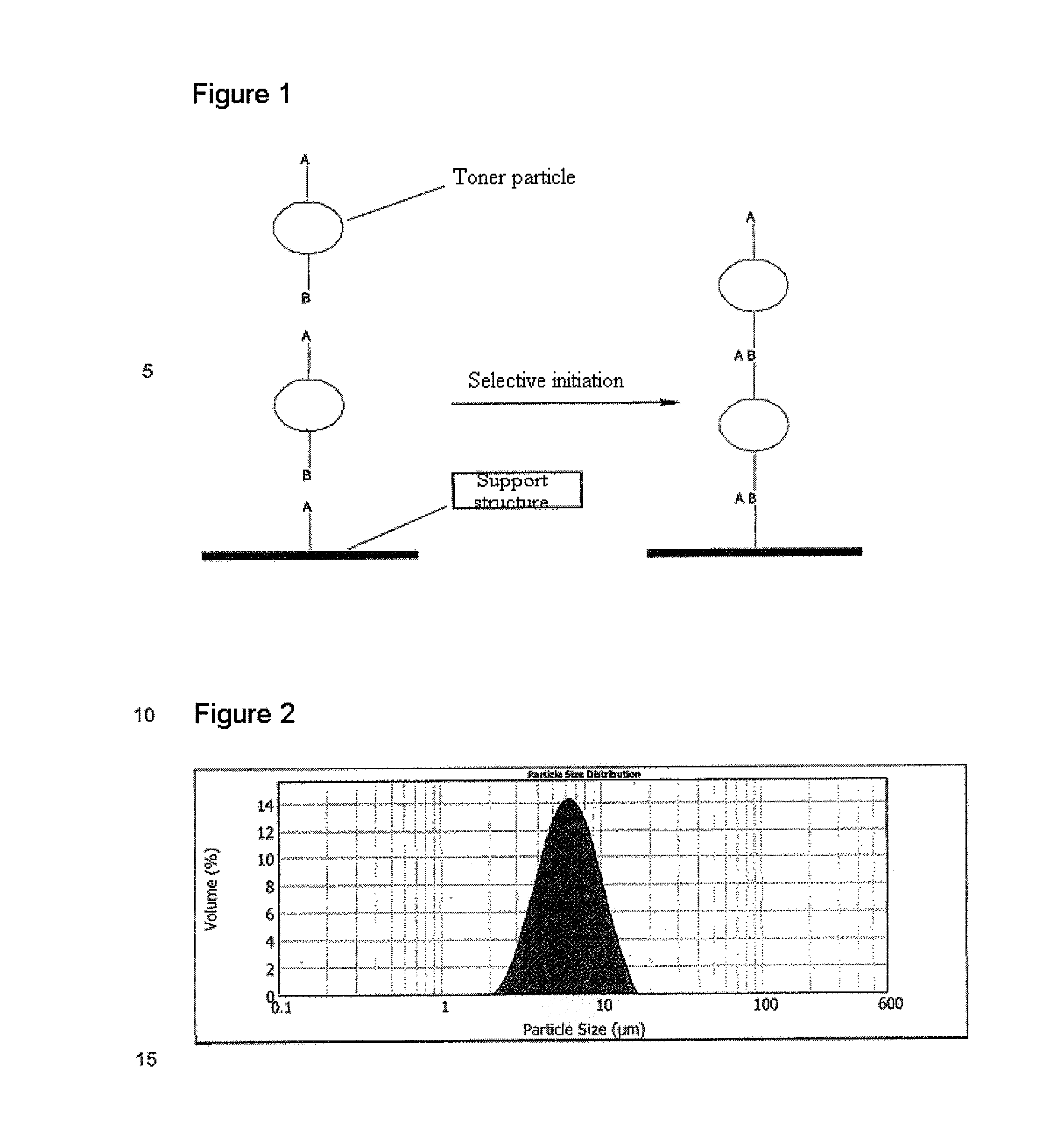
The present invention relates to polymer particles that have functional groups A and B, which can react with each other to form covalent bonds. These particles can be fixed onto a support structure by printing them onto the surface of a support structure and reacting them with complementary functional groups A or B on other polymer particles. The resulting structures have high resolution and can be formed without the need for additional photoinitiators. The invention also allows for the selective fixing of different polymer particles, resulting in the buildup of three-dimensional structures with various materials. The process uses electrophotographic processes and can create porous or non-porous structures, such as tubes or blood vessels. The invention also enables controlled and selective fixing of polymer particles without deformation or reduction in resolution. The use of a printing apparatus allows for multiple print coating and the formation of multilayer systems.

Problems solved by technology

The demand for components formed from several component parts and the increasingly complex geometry thereof increases the requirements with regard to the spatial resolution of the manufacturing process.
Particularly in medical technology, the specific manufacture of transplants is associated with great complexity, since the objects have to be matched individually to each patient.
However, these processes are either restricted to the application of a single polymer component or have resolutions above >250 μm.
However, the resolution cannot be controlled adequately and is restricted to the toner layer present on the support structure.
This method therefore does not offer the possibility of generating a three-dimensional object layer by layer.
However, these processes achieve solely improved adhesion on the support structure surface and do not ensure the controlled three-dimensional buildup of polymer layers.
However, the use of such processes for biologically and medically usable three-dimensional plastic parts is a problem which has not been solved to date, particularly owing to the need for three-dimensional fixing of the individual particles (U.S. Pat. No. 6,066,285 A).

Method used


Image

  • Process of making a three-dimensional structure on a support structure
  • Process of making a three-dimensional structure on a support structure

Examples


example 1

[0105]2.0 g of poly(MMA-co-VAc) particles were dispersed in 50 ml of H2O, and then 5 ml of glacial acetic acid were added. The suspension was stirred for 1 h to hydrolyze the surface of the polymer particles. Thereafter, the particles were filtered off and washed three times each with 20 ml of phosphate buffer (pH=7) and with 20 ml of H2O. Thereafter, the particles were dried under reduced pressure for 4 h. The surface-activated particles were dispersed in 90 ml of n-hexane, and a solution of 3.39 ml (3.13 g) of dimethylallylsilyl chloride in 10 ml of n-hexane was added dropwise.

[0106]The particles were filtered off and washed three times with 20 ml of n-hexane, and dried under reduced pressure for 2 h. The particles were redispersed in 50 ml of H2O, and 4.45 g of EDCHCl were added. Subsequently, 1.79 g of cysteamine were added and the suspension was stirred at RT (room temperature) for 24 h. Thereafter, the particles were filtered off, washed five times with 20 ml each time of H2O ...

example 2

[0107]a) 3.0 g of poly(MMA-co-GMA) particles were dispersed in 75 ml of toluene and the suspension was cooled to 0° C. Subsequently, a solution of 1.68 g of propargylamine in 5 ml of toluene was added dropwise over the course of 20 min. After the suspension had been stirred for 1 h, a solution of 8.87 g of (11-azidoundecyl)chlorodimethylsilane in 25 ml of n-hexane was added and the reaction mixture was warmed to RT. After 4 h, the particles were filtered off and washed five times with 50 ml each time of n-hexane. Thereafter, the particles were dried under reduced pressure for 2 h and then redispersed in 200 ml of a 1% copper(I) salicylate solution for 5 min. Then the polymer particles were filtered off and dried unwashed under reduced pressure for 6 h. Subsequently, the q / m ratio was adjusted with 40 mg of TX-20 silica to a value of −10 μC / g to −30 μC / g, and the particles were printed with an OKI C7000 printer. The support structure used was a glass plate (20×20 cm) which had been t...


PUM

PropertyMeasurementUnit
sizeaaaaaaaaaa
softening temperatureaaaaaaaaaa

Abstract

The present disclosure relates to polymer particles comprising a polymer matrix having a coating of an inorganic semimetal oxide or metal oxide, wherein the polymer matrix has at least one first functional group A and at least one second functional group B, both functional groups A and B being able to enter into at least one covalent bond with one another, functional group A being selected from the group consisting of an azide group, C —C double bond, C —C triple bond, aldehyde group, ketone group, imine group, thioketone group and thiol group, and functional group B being selected from the group consisting of a C —C double bond, C —C triple bond, C —N triple bond, diene group, thiol group and amine group.

Description

CROSS REFERENCE TO RELATED APPLICATIONS[0001]The present application is a 35 U.S.C. §371 National Phase conversion of PCT / EP2011 / 004508, filed Sep. 7, 2011, which claims benefit of German Application No. 10 2010 045 679.9, filed Sep. 17, 2010, the disclosure of which is incorporated herein by reference. The PCT International Application was published in the German language.BACKGROUND OF THE INVENTION[0002]1. Technical Field of the Invention[0003]The present invention relates to polymer particles which are especially suitable as toner particles for electrophotographic processes, to electrophotographic processes for production of three-dimensional structures on a support structure, and to the three-dimensional structures produced by means of these processes.[0004]2. Related Art[0005]The manufacture of three-dimensional objects with the aid of computer-generated models is constantly gaining significance. This involves regular buildup layer by layer, which enables individual matching of...

Claims


Application Information

Patent Timeline
Patent Type & Authority Patents(United States)
IPC IPC(8): B29C35/08B29C41/02G03G15/22G03G13/20G03G9/097G03G9/093G03G9/08G03G9/087
CPCG03G9/0819G03G9/0825G03G9/08708G03G9/08724G03G9/08728G03G9/08753G03G9/08755G03G9/08759G03G9/08771G03G9/08791G03G9/08793G03G9/08795G03G9/09708G03G9/09725G03G13/20G03G15/224G03G9/09364G03G9/09342Y10T428/24893
Inventor HIRTH, THOMASWEBER, ACHIMBORCHERS, KIRSTENGUTTLER, STEFAN
Owner FRAUNHOFER GESELLSCHAFT ZUR FOERDERUNG DER ANGEWANDTEN FORSCHUNG EV
Learn More