
Electrolytic capacitor

a technology of electrolytic capacitor and capacitor, applied in the direction of liquid electrolytic capacitor, capacitor dielectric layer, transportation and packaging, etc., can solve the problems of poor repair efficiency of solid electrolytic capacitor, increased leakage current, short circuit, etc., and achieves low esr, small size, and large capacitance

Active Publication Date: 2015-12-08
PANASONIC INTELLECTUAL PROPERTY MANAGEMENT CO LTD
View PDF53 Cites 15 Cited by
  • Summary
  • Abstract
  • Description
  • Claims
  • Application Information

AI Technical Summary

Benefits of technology

This configuration allows for a small-sized, high-capacitance electrolytic capacitor with low equivalent series resistance (ESR) and enhanced reliability, effectively preventing increased leakage current and short-circuit occurrences under high-temperature conditions.

Problems solved by technology

However, the solid electrolytic capacitor is poor in repairing a defective part in anodic oxide film as a dielectric body.
Therefore, leakage current may increase, and, in the worst case, a short circuit may occur.
Therefore, these electrolyte solutions cannot be used compatibly.
On the other hand, the hybrid-type electrolytic capacitor is used in a smoothing circuit and a control circuit at the power supply output side because it has an ESR as low as that of a solid-type electrolytic capacitor and has a limitation with respect to a withstand voltage.
Electrolytic capacitors used in AV apparatuses and automobile electrical equipment require high reliability over a long period of time.
However, if the electrolytic capacitor is used for a long time beyond the guaranteed lifetime, a solvent in the electrolyte solution is finally lost.
Therefore, a function of self-repairing a defective part in the dielectric oxide film is lost.
Therefore, when an effect of the electrolyte solution is lost, an increase in leakage current is caused.
As a result, in a worst case, a short circuit occurs.

Method used


Image

  • Electrolytic capacitor
  • Electrolytic capacitor
  • Electrolytic capacitor

Examples


Embodiment Construction

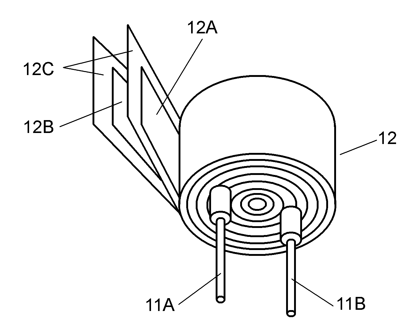
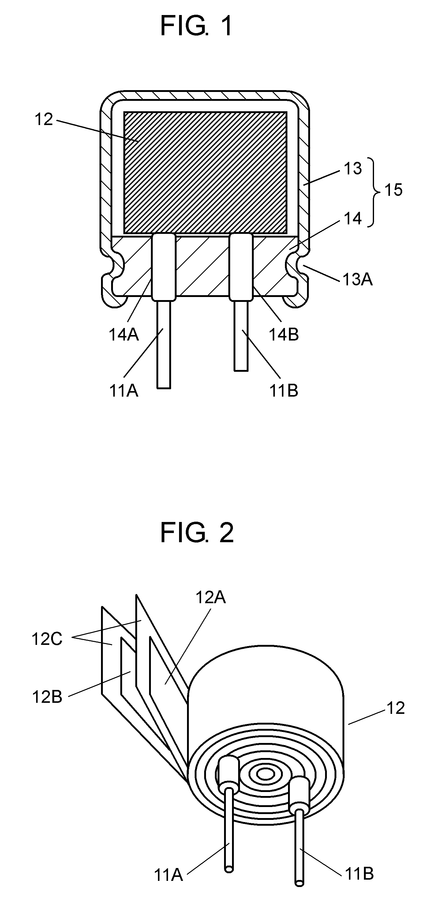
[0025]Firstly, a configuration of an electrolytic capacitor in accordance with this exemplary embodiment is described with reference to FIGS. 1 and 2. FIG. 1 is a sectional view showing a configuration of a hybrid-type electrolytic capacitor (having wound-type capacitor element) of an example of an electrolytic capacitor in accordance with an exemplary embodiment of the present invention, and FIG. 2 is a developed perspective view of a capacitor element of the hybrid-type electrolytic capacitor.

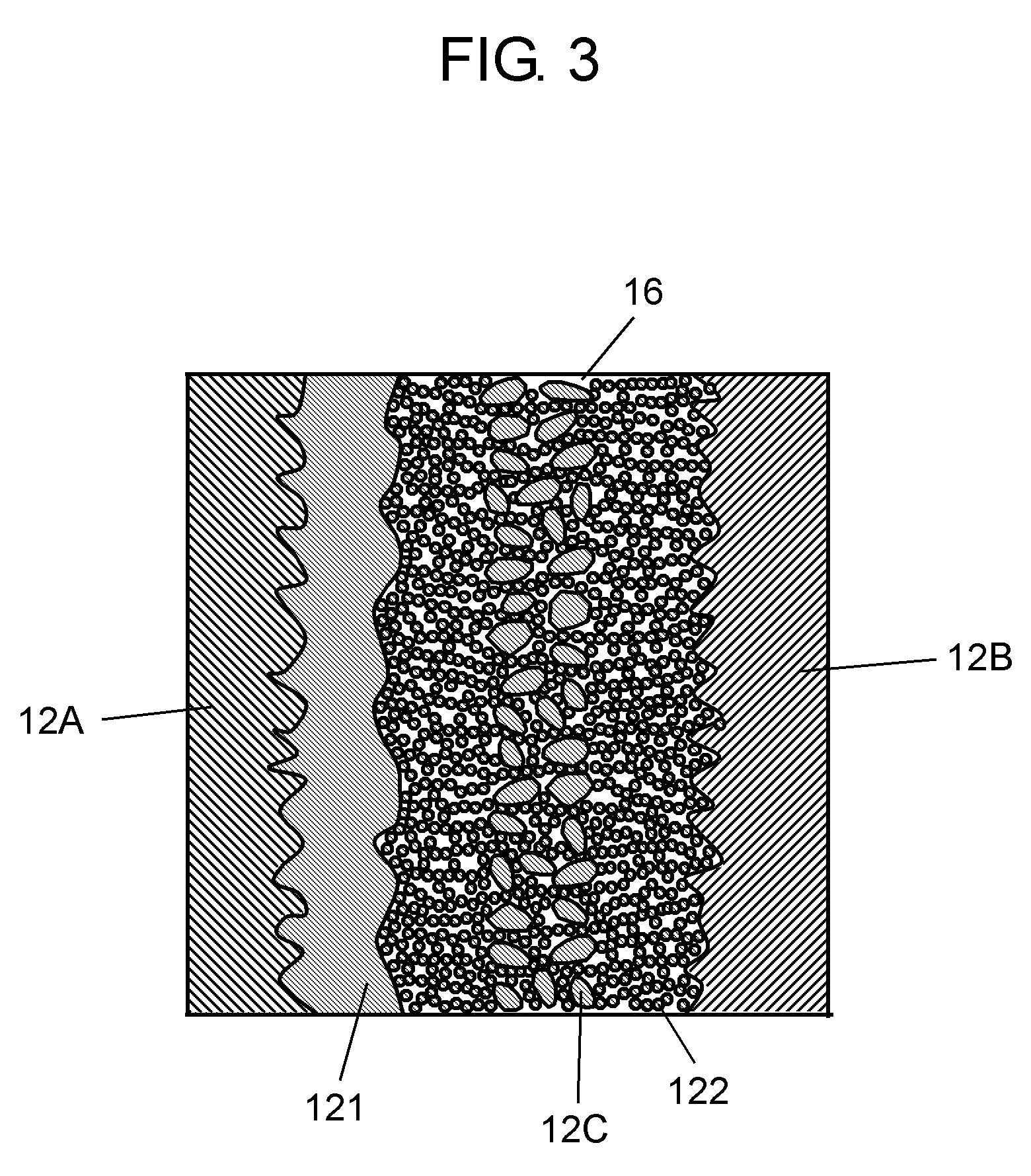
[0026]As shown in FIG. 1, the electrolytic capacitor includes capacitor element 12, first lead wire 11A and second lead wire 11B (hereinafter, referred to as “lead wires 11A and 11B”), and outer package 15. As shown in FIG. 2, capacitor element 12 includes anode foil 12A, cathode foil 12B, and separator 12C disposed between anode foil 12A and cathode foil 12B. Lead wire 11A is connected to node foil 12A, and lead wire 11B is connected to cathode foil 12B. That is to say, one end portion of le...


PUM

PropertyMeasurementUnit
temperatureaaaaaaaaaa
heightaaaaaaaaaa
diameteraaaaaaaaaa

Abstract

An electrolytic capacitor includes a capacitor element, an electrolyte solution with which the capacitor element is impregnated, and an outer package enclosing the capacitor element and the electrolyte solution. The capacitor element includes an anode foil having a dielectric layer on a surface thereof, a cathode foil, a separator disposed between the anode foil and the cathode foil, and a solid electrolyte layer in contact with the dielectric layer of the anode foil and the cathode foil. The electrolyte solution contains a low-volatile solvent that is at least one of polyalkylene glycol and a derivative of polyalkylene glycol.

Description

TECHNICAL FIELD[0001]The present invention relates to an electrolytic capacitor used in various electronic apparatuses.BACKGROUND ART[0002]With digitalization of electronic apparatuses, there is a demand for capacitors having a small size, a large capacitance, and a small equivalent series resistance (hereinafter, abbreviated as “ESR”) in a high frequency region to be used at a power supply output side of circuits such as, for example, a smoothing circuit and a control circuit. As such capacitors, electrolytic capacitors using a fluid electrolyte typically such as an electrolyte solution have been used. Furthermore, recently, solid electrolytic capacitors using a solid electrolyte such as manganese dioxide, a TCNQ complex salt, or an electroconductive polymer such as polypyrrole, polythiophene, and polyaniline have been used.[0003]The solid electrolytic capacitor is excellent in that it has a particularly low ESR as compared with a liquid-type electrolytic capacitor. However, the so...

Claims


Application Information

Patent Timeline
Patent Type & Authority Patents(United States)
IPC IPC(8): H01G9/022H01G9/035H01G11/60H01G11/64H01G11/62
CPCH01G9/035H01G11/60H01G11/62H01G11/64Y02E60/13Y02T10/7022H01G9/055H01G9/07H01G9/145Y02T10/70H01G9/15H01G11/04H01G11/24
Inventor MATSUURA, HIROYUKIFURUSAWA, SHIGETAKASASAKI, HIDEHIROAOYAMA, TATSUJI
Owner PANASONIC INTELLECTUAL PROPERTY MANAGEMENT CO LTD
Learn More