Cladding material, tube including such cladding material and methods of forming the same

a technology of cladding material and cladding tube, which is applied in the direction of nuclear engineering, nuclear elements, pipes, etc., can solve the problems of corrosion of fuel cladding tube formed from zirconium-based alloys in the life-limiting use of fuel cladding tubes currently available, and achieve the effect of reducing operation costs and increasing safety

Active Publication Date: 2016-03-01
ADVANCED CERAMIC FIBERS
View PDF86 Cites 11 Cited by
  • Summary
  • Abstract
  • Description
  • Claims
  • Application Information

AI Technical Summary

Problems solved by technology

Increased demands on such components are in the form of longer required residence times, thinner structural members and increased power output per area, which cause corrosion.
While zirconium and other metal alloys have excellent corrosion resistance and mechanical strength in a nuclear reactor environment under normal and accident conditions where the heat fluxes are relatively low, they encounter mechanical stability problems during conditions such as a departure from nucleate boiling (“DNB”) incident that might occur during accidental conditions.
A significant in-reactor life limiting use with currently available fuel cladding tubes formed from zirconium-based alloys is corrosion, especially in the presence of water and increased operating temperatures of newer generations of nuclear reactors, such as light water reactors (LWRs) and supercritical water cooled reactors (SCWRs).
For example, buildup of oxide material on the fuel cladding tubes caused by oxidation of zirconium during reactor operation may lead to adverse effects on thermal conduction.
The presence of the precipitates may reduce mechanical strength of the fuel cladding tube causing cracks in walls and end caps.
Fuel cladding tubes formed from zirconium and zirconium alloys are also susceptible to stress corrosion cracking during operation due to joint action of fission precuts and mechanical stress resulting from radiation-induced swelling of fuels.
The interaction between the fuel and the cladding results in nucleation and propagation of cracks and depressurization of the fuel cladding tube.
Such cracks propagate from an internal surface of the fuel cladding tube to an external surface and, thus, may rupture the cladding wall.
Depressurization of the fuel cladding tube due to stress corrosion cracking significantly reduces the life of the fuel cladding tube and, in addition, reduces the output and safety of the nuclear reactor.
Deformation of the fuel cladding tube resulting from such tension increases susceptibility of the fuel cladding tube to stress corrosion failure.
The silicon carbide fuel cladding tubes are porous structures that are difficult to achieve reliable hermetic sealed around the nuclear fuel.
Thus, ceramic material debris dislodged from the silicon carbide fuel cladding tubes during use may reside between the fuel and the ceramic cladding and may be a source of local stress concentration during normal fuel swelling.
The release of such ceramic material debris causes localized thermal and mechanical damage in the silicon carbide fuel cladding tubes, eventually causing failure thereof.

Method used


Image

  • Cladding material, tube including such cladding material and methods of forming the same
  • Cladding material, tube including such cladding material and methods of forming the same
  • Cladding material, tube including such cladding material and methods of forming the same

Examples


Embodiment Construction

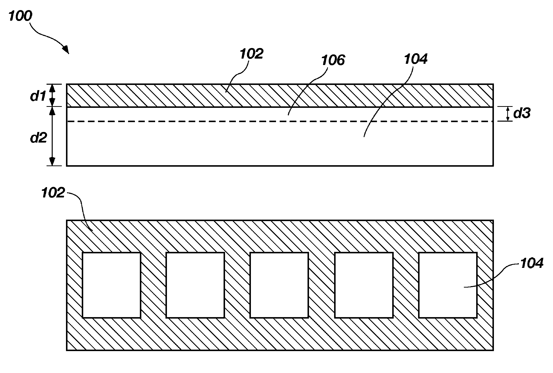
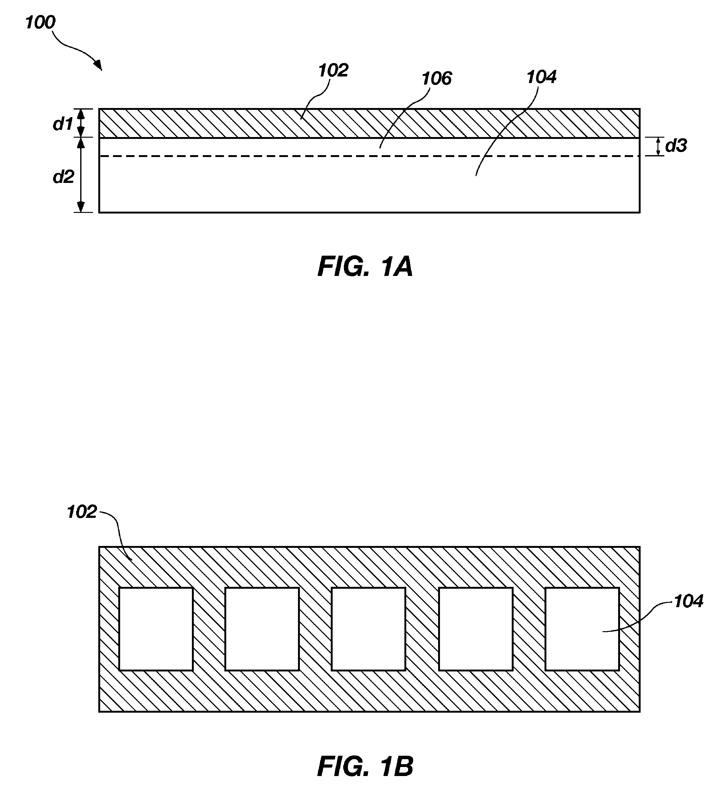
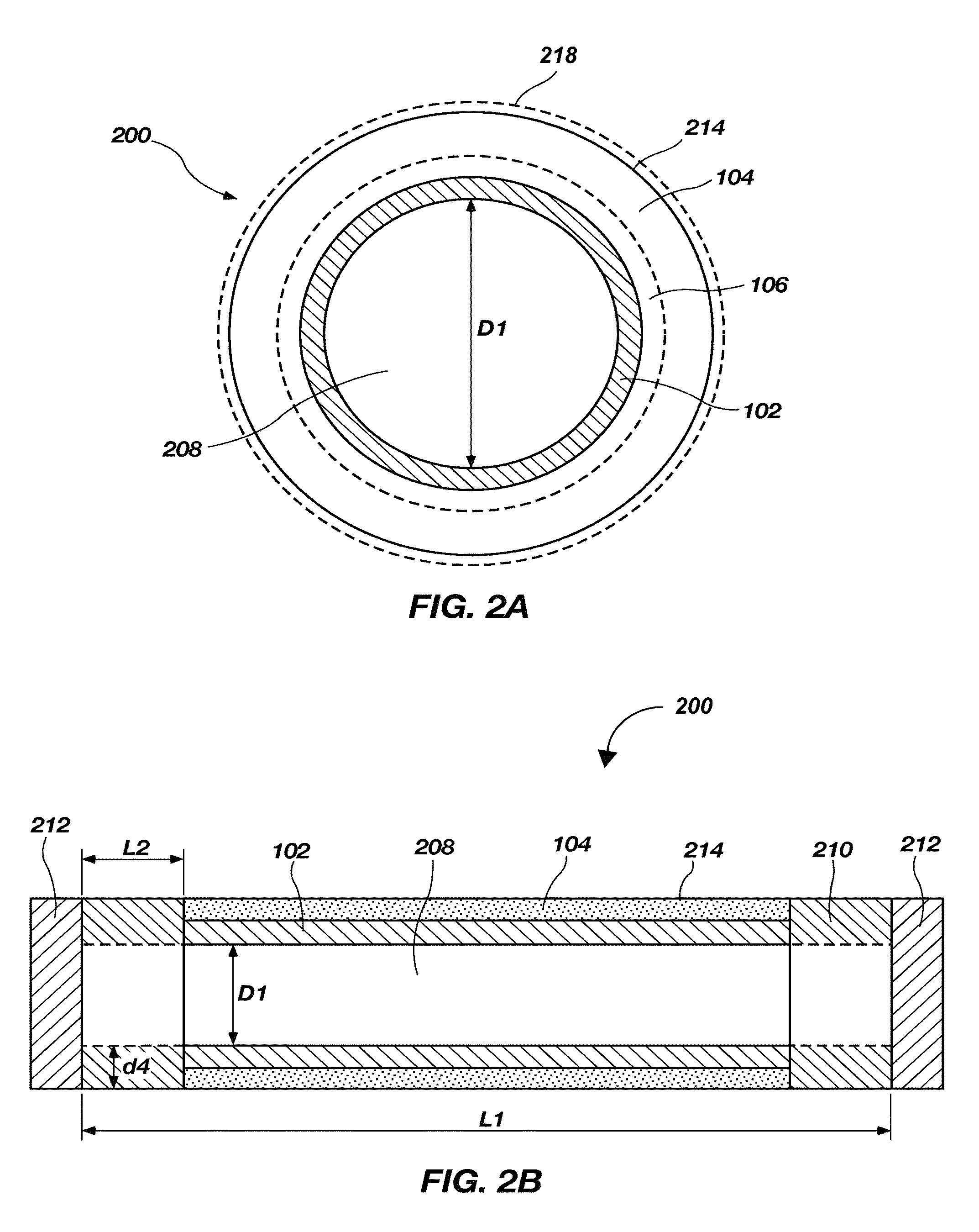
[0019]Embodiments of the present disclosure related to a cladding material that may be used in a containment vessel, such as a fuel tube, for nuclear fuel (i.e., fissile material), used in a nuclear power plant or other reactor or used in an industrial process. The cladding material may have a multi-layered structure including a metallic material that includes a zirconium alloy and a ceramic matrix composite (CMC) layer that includes continuous silicon carbide fibers and a matrix comprising a silicon carbide ceramic. The cladding material may be used to form a multi-layered tube that includes the metallic material as an inner liner and the ceramic matrix composite as an outer support. The multi-layered tube may be used, for example, as a fuel cladding tube for a nuclear reactor, a chemical processing heat exchanger, a steam generator, a gas phase cooling system, a radiator or a combustion chamber liner. The multi-layered tube may further include an outer metallic liner that may, opt...


PUM

PropertyMeasurementUnit
thicknessaaaaaaaaaa
thickness d1aaaaaaaaaa

Abstract

A multi-layered cladding material including a ceramic matrix composite and a metallic material, and a tube formed from the cladding material. The metallic material forms an inner liner of the tube and enables hermetic sealing of thereof. The metallic material at ends of the tube may be exposed and have an increased thickness enabling end cap welding. The metallic material may, optionally, be formed to infiltrate voids in the ceramic matrix composite, the ceramic matrix composite encapsulated by the metallic material. The ceramic matrix composite includes a fiber reinforcement and provides increased mechanical strength, stiffness, thermal shock resistance and high temperature load capacity to the metallic material of the inner liner. The tube may be used as a containment vessel for nuclear fuel used in a nuclear power plant or other reactor. Methods for forming the tube comprising the ceramic matrix composite and the metallic material are also disclosed.

Description

STATEMENT REGARDING FEDERALLY SPONSORED RESEARCH OR DEVELOPMENT[0001]This invention was made with government support under Contract Number DE-AC07-05ID14517 awarded by the United States Department of Energy. The government has certain rights in the invention.CROSS-REFERENCE TO RELATED APPLICATION[0002]This application is related to U.S. patent application Ser. No. 12 / 901,309 to Gamier et al., entitled “METHODS OF PRODUCING SILICON CARBIDE FIBERS, SILICON CARBIDE FIBERS, AND ARTICLES INCLUDING SAME,” assigned to the Assignee of the present application and filed on even date herewith, the disclosure of which is incorporated by reference herein in its entirety.TECHNICAL FIELD[0003]The invention, in various embodiments, relates generally to cladding material for use in nuclear reactors, tubes formed from such cladding material, and to methods of forming such tubes. More particularly, embodiments of the invention relate to tubes including an inner metallic material surrounded by fiber re...

Claims


Application Information

Patent Timeline
Patent Type & Authority Patents(United States)
IPC IPC(8): G21C3/00C04B35/573C04B35/571C04B35/565G21C3/07F16L9/10F16L9/14C04B37/02C04B35/80C04B35/628F22B37/00F16L58/14F22B37/06G21C13/028
CPCG21C3/07C04B35/565C04B35/571C04B35/573C04B35/62863C04B35/806C04B37/021C04B37/025F16L9/10F16L9/14F16L58/14F22B37/002C04B2235/9684C04B2237/062C04B2237/08C04B2237/365C04B2237/38C04B2237/40C04B2237/403C04B2237/405C04B2237/406C04B2237/60C04B2237/62C04B2237/704C04B2237/706C04B2237/708C04B2237/84F22B37/06F23M2900/05004G21C13/028Y02E30/40C04B2235/3251C04B2235/3258C04B2235/3409C04B2235/3427C04B2235/383C04B2235/3821C04B2235/3826C04B2235/3834C04B2235/3839C04B2235/3843C04B2235/3847C04B2235/3891C04B2235/428C04B2235/524C04B2235/5228C04B2235/5244C04B2235/5248C04B2235/5252C04B2235/5256C04B2235/5268C04B2235/616C04B2235/9607C04B35/80Y02E30/30
Inventor GARNIER, JOHN, E.GRIFFITH, GEORGE, W.
Owner ADVANCED CERAMIC FIBERS
Why Eureka
Try Eureka