
Nanoparticle composition, a device and a method thereof

Inactive Publication Date: 2016-04-26
KENT STATE UNIV
View PDF11 Cites 0 Cited by
  • Summary
  • Abstract
  • Description
  • Claims
  • Application Information

AI Technical Summary

Benefits of technology

This patent describes a new method for assembling nanoparticles using a special material called a chromonic material. This method allows for the formation of both side-by-side and end-to-end connections between nanoparticles. The use of chromancs as linkers has several advantages, including not requiring covalent functionalization of the nanoparticles, allowing for more flexibility in the process. The chromonic materials can withstand higher temperatures than DNA and proteins and are relatively cheap. The method also uses a fundamentally different approach compared to existing methods. The degree of nanoparticle assembly can be controlled by changing the concentration or pH of the chromonic material. The invention also includes a method for dynamic control of the assembly process using a quencher. The use of dynamic light scattering (DLS) and the refractive index of water are used to determine the size and shape of the assembled nanoparticles.

Problems solved by technology

Understanding and controlling the collective behavior of nanoparticles (NPs) is a challenging task of fundamental and practical importance.

Method used


Image

  • Nanoparticle composition, a device and a method thereof
  • Nanoparticle composition, a device and a method thereof
  • Nanoparticle composition, a device and a method thereof

Examples


example 1

Side-by-Side Assembly

[0041]Gold NRs of average aspect ratio 3 (length 45 nm and diameter 15 nm) were synthesized by using the seed mediated growth method reported by B. Nikoobakht, M. A. El-Sayed, Chem. Mater. 2003, 15, 1957-1962. The experiments were then performed with these Au NRs coated with CTAB, which imparted a positive charge to the rods. A 20 ml solution of gold NRs was centrifuged twice and redispersed into a final volume of 1 ml of deionized water to remove excess CTAB stabilizer from the solution. The purified gold NRs had a bilayer of surfactant on the surface and a net positive charge (zeta potential+30 mV).

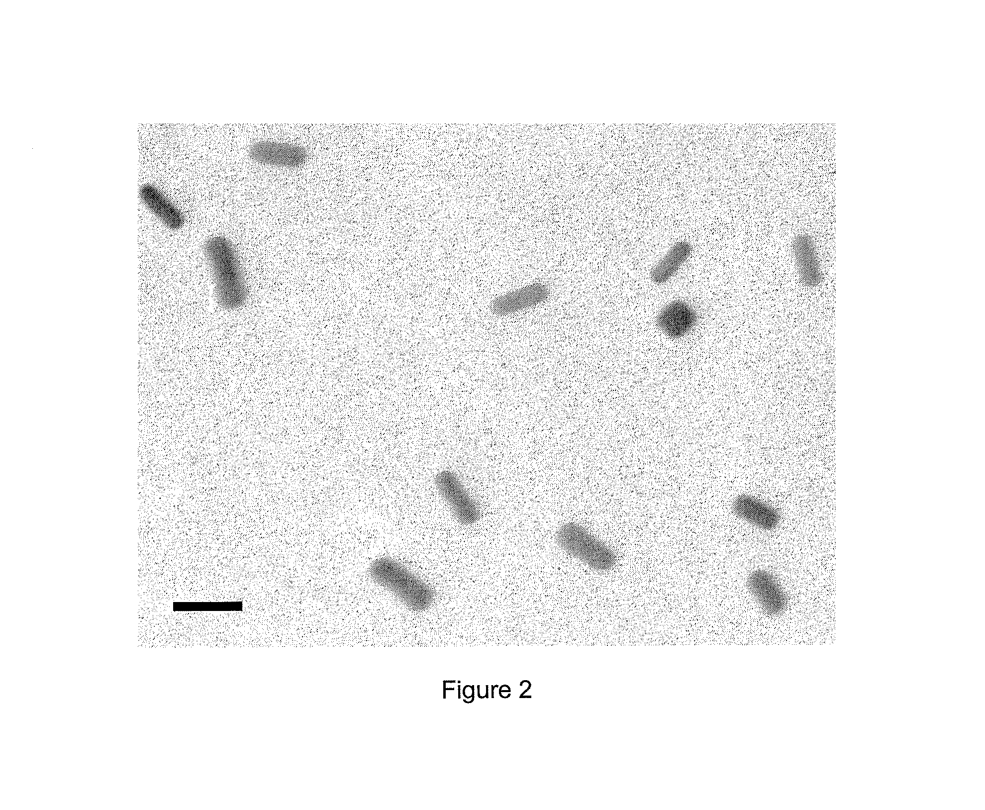
[0042]In control samples with no DSCG added, no self-assembly was observed as the gold NRs repel each other. As shown in the TEM image of FIG. 2, the NRs appear isolated in the absence of DSCG.

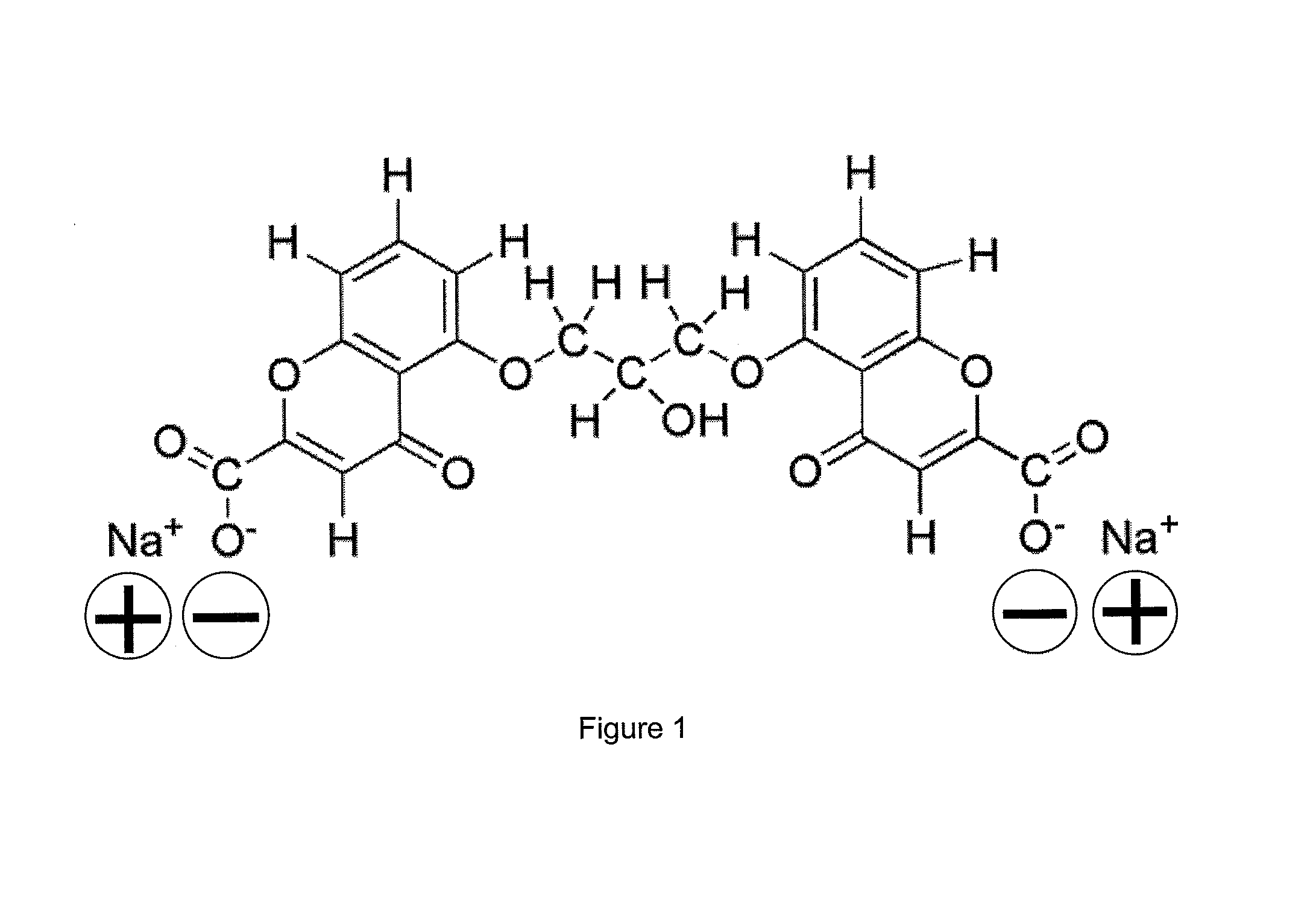
[0043]Side-by-side self-assembly of Au NRs was induced by mixing a 0.8 mM DSCG solution mixed with 2 nM Au NR solution in water in a 1:1 ratio. 1 ml of DSCG solution in water ...

example 2

End-to-End Assembly

[0054]This Example was conducted similarly to Example 1, except that, to make the gold NRs negatively charged, 100 μl of 1% polyacrylic acid (PAA) (Mol. Wt. 400,000) solution in water was slowly added to 1 ml of the purified gold nanorod solution under vigorous stirring. The negatively charged PAA was adsorbed onto the positively charged gold NRs by electrostatic attraction and the excess COOH groups provide a net negative charge to the rods (zeta potential −25 mV).

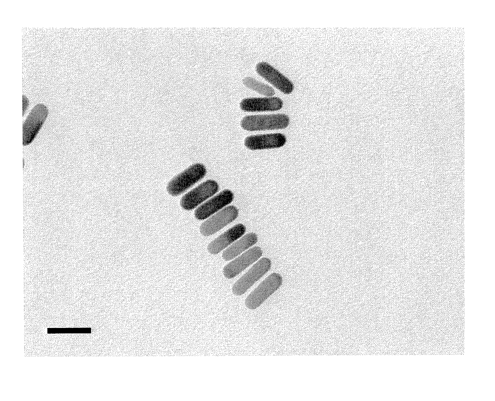
[0055]End-to-end self assembly of Au NRs with CTAB and PAA coatings was induced by 0.1 M DSCG added to 2 nM Au NR solution in water in 1:1 proportion. TEM images of the end-to-end chains were taken about 6 hours (FIGS. 8 and 9) and 24 hours (FIG. 10) after the mixture preparation. FIG. 11 schematically represents the end-to-end assembly of Au NRs 111 with CTAB and PAA coatings induced by the addition of DSCG 112. FIG. 12 shows the time evolution of the absorption spectrum of the Au NR solution after 0.1...

example 3

Quench Gold NR Assembly by Polymer Coating

[0059]A key challenge in producing the NR assemblies is to control their size, because the size of the assembled NR structures increases with time, resulting in giant clusters that eventually precipitate. In this Example, the growth of chromonic-mediated side-by-side NR assemblies was arrested by using polyelectrolytes.

[0060]In preparing a solution of NRs and DSCG similar to Example 1, 1% of PSS solution was added to the NR solution in the ratio of 1:4 at 0, 5, 15, 30, 60 and 120 minutes after DSCG was added. After the addition of the polyelectrolyte, the longitudinal and transverse plasmon peaks stopped shifting. After removing the excess polymer and DSCG by centrifugation, the resulting NR solutions demonstrate “arrested” spectral features that are stable for a period of at least one month, as shown in FIG. 13. FIG. 13 is the absorption spectra of the assembled NR structure with the addition of a 1% PSS solution at different reaction times...


PUM

PropertyMeasurementUnit
aspect ratioaaaaaaaaaa
aspect ratiosaaaaaaaaaa
lengthaaaaaaaaaa

Abstract

A nanoparticle composition, a device including the nanoparticle composition, and a method thereof are provided. The composition comprises nanoparticles such as Gold nanorods (NR) and electrically charged self-assembled molecular aggregates such as disodium chromoglycate (DSCG) in a common solvent such as water. The nanoparticles are assembled as, for example, side-by-side and end-to-end assemblies of nanorods, through a non-covalent interaction such as anisotropic electrostatic interaction with the electrically charged self-assembled molecular aggregates. The invention can be used in a cloaking device, a biological sensing device, a drug delivery, a meta material, a negative index material, an enhanced imaging device, and a device for solar energy conversion, and exhibits many merits such as simpler process without the need of a covalent bonding between the nanoparticles, different manners of nanoparticles assembling with same linker, higher thermal stability, cost effectiveness, and capability of gradual controlling of the degree of NR assembly, among others.

Description

[0001]This application claims priority based on the U.S. Provisional Application 61 / 190,014 filed on Aug. 25, 2008, which is incorporated herein by reference in its entirety.[0002]This invention was made with United States Government Support under Grant No. FA9550-06-1-0337 from the Air Force Office of Scientific Research, Multidisiplinary University Research Initiative; Grant No. DMR-0504516 from the W. Keck Foundation, National Science Foundation; Grant No. N00014-06-1-0473 from the Office of Naval Research; Grant Nos. GRT00008581 / RF60012388 and FA9550-05-1-043 from the Air Force Office of Scientific Research; and Grant No. CMS-0528867 from the National Science Foundation. The United States Government has certain rights in this invention.BACKGROUND OF THE INVENTION[0003]The present invention is related to a nanoparticle composition, a device including the nanoparticle composition, and a method thereof. It finds particular application in conjunction with a cloaking device, a biolog...

Claims


Application Information

Patent Timeline
Patent Type & Authority Patents(United States)
IPC IPC(8): H01B1/22H01B1/02B22F1/00B82Y30/00B22F1/0545
CPCB22F1/0022B22F1/0025B82Y30/00H01B1/02H01B1/22B22F1/0547B22F1/0545
Inventor LAVRENTOVICH, OLEG D.PARK, HEUNG-SHIK
Owner KENT STATE UNIV
Learn More