
Eureka
For R&D, Eureka makes reading and utilizing patents & technical documents easy.
Eureka AIR
Designed for self-driven R&D workflows. Generate viable solutions, solve complex R&D challenges, empower your innovation with AI.

Eureka Materials
Designed for material experts only. Revolutionize your material R&D, from search, analyze, to developing new materials.

TechResearch
Generate reliable direction feasibility study reports for your R&D in just a few steps.

TechSeek
Discover and master advanced knowledge NOW. Basics, ideas, possibilities, all at once.

TechMind
As an expert in R&D Theories, TechMind can generates customized viable solutions instantly.

TechRisk
Analyze your overall solution with one click, know your potential R&D risks in advance.

TechMonitor
Get weekly tech updates, stay abreast of the latest tech innovations and key insights.
Ultra-porous photocatalytic material, method for the manufacture and the uses thereof
- Summary
- Abstract
- Description
- Claims
- Application Information
AI Technical Summary
Benefits of technology
Problems solved by technology
Method used
Image

Examples
example
Example 1
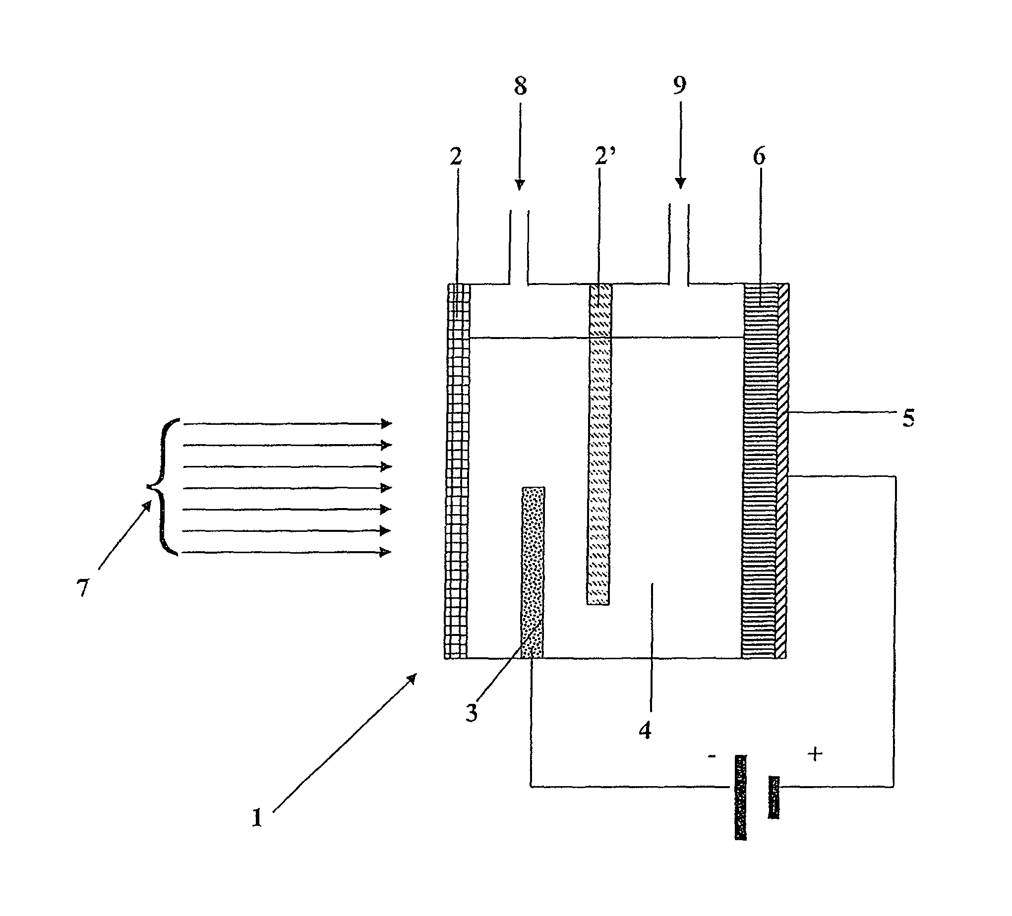
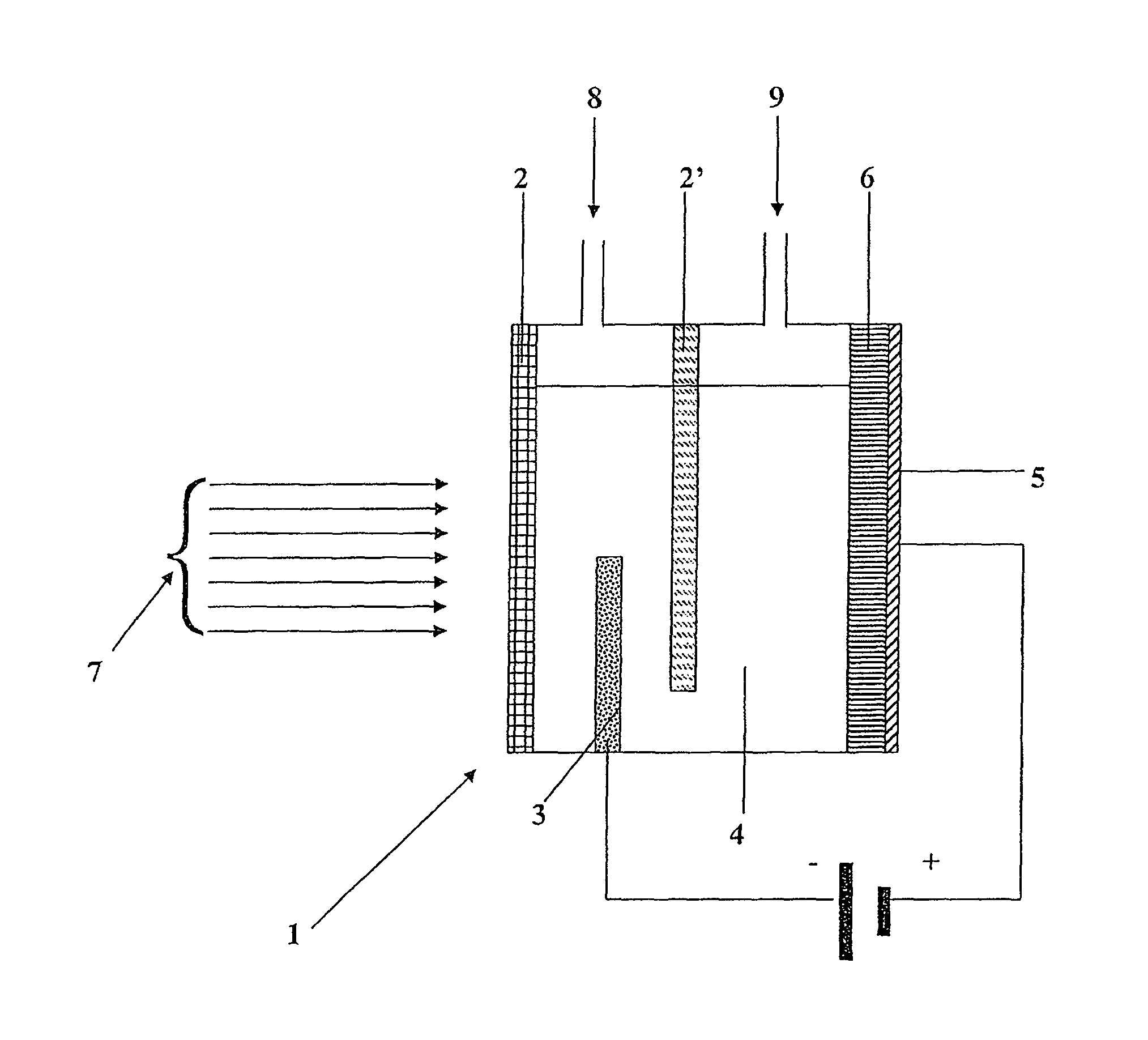
[0094]A cell for the production of hydrogen, denoted (1) in FIG. 1, comprising two glass walls, denoted (2) and (2′) in FIG. 1, was prepared. The cell (1) is divided into two compartments, separated from one another by the glass wall (2′). In this cell, the cathode, denoted (3) in FIG. 1 and situated between the glass walls (2) and (2′), is composed of a platinum wire dipped in the electrolyte (acidulated water), denoted (4) in FIG. 1. Thus, the compartment defined between the walls (2) and (2′) is referred to as cathode compartment and the compartment defined between the wall (2′) and the substrate, denoted (5) in FIG. 1, which acts as anode, is referred to as anode compartment.
[0095]A layer of composite material, precursor of the photo-catalytic material, denoted (6) in FIG. 1, with a thickness of 3 μm, is deposited on the substrate (5), said substrate being in this instance a silicon wafer (diameter 100 mm, thickness 500 μm, resistivity in the range 10-20 Ω.cm), accordin...
example 2
[0107]A series of samples was produced by depositing by cathode sputtering on a titanium substrate, at a temperature of 300° C., a composite material comprising an atomic percentage of titanium of 50% and an atomic percentage of aluminum of 50%. The thickness of the film deposited is 1 μm.
[0108]Another series of samples was prepared by depositing by cathode sputtering, also on a titanium substrate, at a temperature of 100° C., a film having the same thickness (1 μm) of a composite material having the same composition as above.
[0109]The two series of samples were subsequently modified according to the same protocol, by undergoing:[0110]a stage of electrochemical anodization in a dilute sulfuric acid H2SO4 solution (10% by volume, i.e. approximately 2 mol.l−1), under a current density of 10 mA.cm−2, then[0111]a stage of removal of the aluminum oxide Al2O3 formed by selective chemical attack, by bringing into contact with a dilute phosphoric acid H3PO4 solution (50% by volume, i.e. app...
example 3
[0132]A series of samples was produced by depositing by cathode sputtering on a titanium substrate, at a temperature of 300° C., a composite material comprising an atomic percentage of titanium 50% and an atomic percentage of aluminum of 50%. The thickness of the film deposited is 1 μm.
[0133]Another series of samples was prepared by depositing by cathode sputtering, also on a titanium substrate, at a temperature of 100° C., a film having the same thickness (1 μm) of a composite material having the same composition as above.
[0134]The two series of samples were subsequently modified according to the same protocol by steeping in a solution comprising 150 ml of 100% acetic acid CH3COOH, 30 ml of 65% nitric acid HNO3, 760 ml of 80% phosphoric acid H3PO4 and 30 ml of water, the samples being kept in this solution for 15 minutes, at a temperature of 35° C.±5° C.
[0135]The two series of samples were subsequently respectively subjected to a thermal annealing at 500° C. and then a thermal anne...
PUM
| Property | Measurement | Unit |
|---|---|---|
| Temperature | aaaaa | aaaaa |
| Temperature | aaaaa | aaaaa |
| Temperature | aaaaa | aaaaa |
Abstract
Description
Claims
Application Information
 - R&D Engineer
- R&D Manager
- IP Professional
- Industry Leading Data Capabilities
- Powerful AI technology
- Patent DNA Extraction
Browse by: Latest US Patents, China's latest patents, Technical Efficacy Thesaurus, Application Domain, Technology Topic, Popular Technical Reports.
© 2024 PatSnap. All rights reserved.Legal|Privacy policy|Modern Slavery Act Transparency Statement|Sitemap|About US| Contact US: help@patsnap.com