
Multinozzle emitter arrays for ultrahigh-throughput nanoelectrospray mass spectrometry

a nanoelectrospray and mass spectrometry technology, applied in the field of electron ionization emitters and emitter arrays for mass spectrometry, can solve the problems of affecting affecting the quality of sample samples, so as to improve the reproducibility of parallel analysis and improve the throughput. , the effect of reducing the cross-contamination of samples

Active Publication Date: 2017-10-17
RGT UNIV OF CALIFORNIA
View PDF18 Cites 3 Cited by
  • Summary
  • Abstract
  • Description
  • Claims
  • Application Information

AI Technical Summary

Benefits of technology

The device described in this patent has several advantages. Firstly, it prevents samples from being contaminated when analyzed because each sample is analyzed by a separate individual emitter. Secondly, the device improves consistency and accuracy when analyzing multiple samples simultaneously because the emitters are highly reproducible and identical to each other. Lastly, the device is made from a robust and inert material, meaning it can be used in various conditions and reused many times by cleaning with harsh chemicals or heating to extreme temperatures. Additionally, the device can be integrated with other components for biosample injection, separation, and processing. Finally, the device can be upgraded by increasing the size of the wafer.

Problems solved by technology

However, samples were processed individually offline and coverage of proteome and metabolome was limited in these studies.
However, hydrophobic polymers have inherently undesirable properties for electrospray, such as a strong affinity to proteins and peptides and incompatibility with certain organic solvents; glass substrates are difficult to fabricate for complex structures; and out-of-plane strategy is critically limited in producing monolithically-integrated devices.
However, these devices have been developed for routine liquid chromatography (LC)-MS / MS applications and lack high-throughput capabilities.
Their wide adoption by the research community remains to be seen because of their high costs and requirements for vendor-designated mass spectrometers.
Performing high-throughput ESI-MS remains a challenge because MS itself has a high capital and operational cost, limiting its scalability.
However, the former has a size in the range of millimeters to centimeters and is not suitable for conventional mass spectrometers.
Furthermore, neither of them is amenable for monolithic integration on a microchip.
However, these devices also have intrinsic limitations in monolithic integration.

Method used


Image

  • Multinozzle emitter arrays for ultrahigh-throughput nanoelectrospray mass spectrometry
  • Multinozzle emitter arrays for ultrahigh-throughput nanoelectrospray mass spectrometry
  • Multinozzle emitter arrays for ultrahigh-throughput nanoelectrospray mass spectrometry

Examples


example 1

Multinozzle Emitter Arrays for Nanoelectrospray Mass Spectrometry

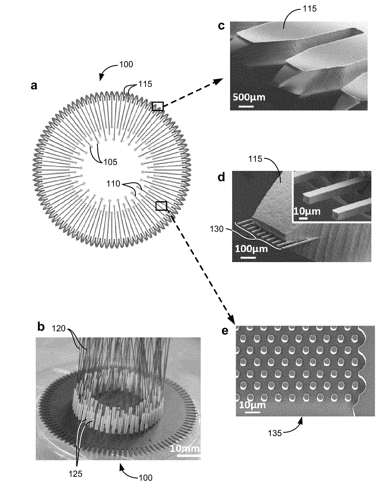
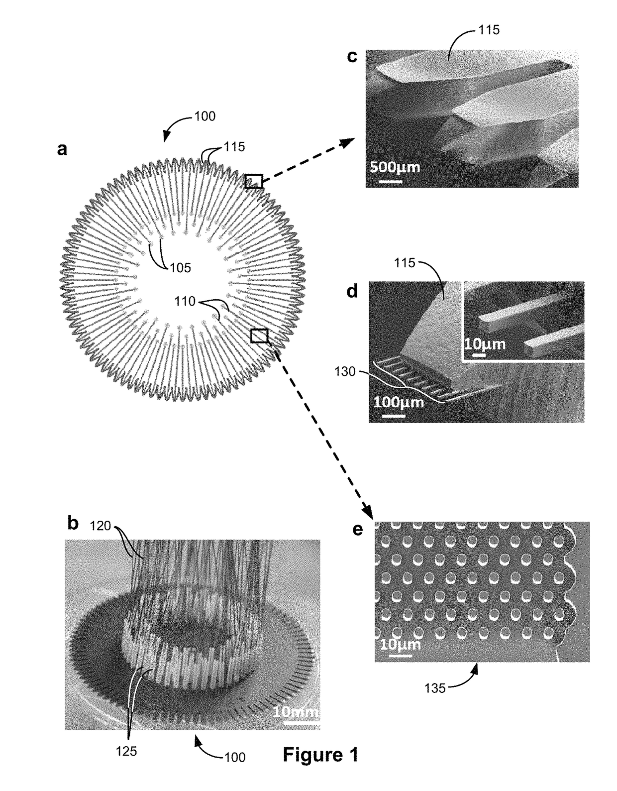
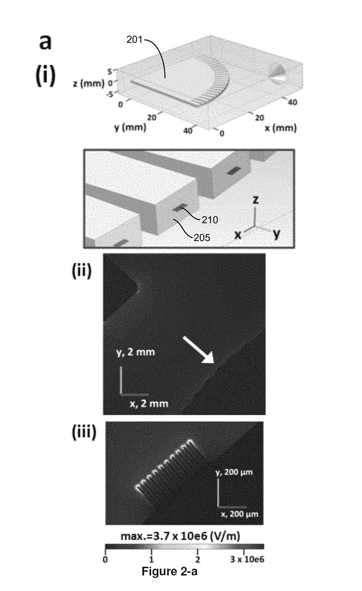
[0072]Mass spectrometry (MS) is the enabling technology for proteomics and metabolomics. However, dramatic improvements in both sensitivity and throughput are still required to achieve routine MS-based single cell proteomics and metabolomics. Here, we report the silicon-based monolithic multinozzle emitter array (MEA), and demonstrate its proof-of-principle applications in high-sensitivity and high-throughput nanoelectrospray mass spectrometry. Our MEA consists of 96 identical 10-nozzle emitters in a circular array on a 3-inch silicon chip. The geometry and configuration of the emitters, the dimension and number of the nozzles, and the micropillar arrays embedded in the main channel, can be systematically and precisely controlled during the microfabrication process. Combining electrostatic simulation and experimental testing, we demonstrated that sharpened-end geometry at the stem of the individual multinozzle emitter ...

example 2

High-Density Microfabricated Multinozzle Emitters for Nanoelectrospray Mass Spectrometry

[0137]We previously developed microfabricated monolithic multinozzle (M3) emitters and demonstrated their applications in nanoelectrospray mass spectrometry1. However, the high operating voltage (4.5 kV) required for electrospray ionization prevented us from implementing high-density multinozzle emitters for mass spectrometry. Combining electrostatic simulation and experimental testing, we showed that sharpened-end geometry at the main channel of the M3 emitters dramatically reduced the operating voltages for the multinozzles (to ˜2-3.5 kV) in the cone-jet mode, comparable to that of commercial silica-based capillary nanoelectrospray tips. This critical improvement enabled us to fabricate and test M3 emitters with high-density nozzle arrays (e.g., 20, 30, 40 nozzles with a linear density of 50˜100 nozzles / mm). We showed increased mass spectrometry sensitivity of these emitters, with an average 3-...


PUM

PropertyMeasurementUnit
thicknessaaaaaaaaaa
thicknessaaaaaaaaaa
thickaaaaaaaaaa

Abstract

The present invention provides for a structure comprising a plurality of emitters, wherein a first nozzle of a first emitter and a second nozzle of a second emitter emit in two directions that are not or essentially not in the same direction; wherein the walls of the nozzles and the emitters form a monolithic whole. The present invention also provides for a structure comprising an emitter with a sharpened end from which the emitter emits; wherein the emitters forms a monolithic whole. The present invention also provides for a fully integrated separation of proteins and small molecules on a silicon chip before the electrospray mass spectrometry analysis.

Description

RELATED PATENT APPLICATIONS[0001]The application claims priority as a continuation application of PCT International Patent Application No. PCT / US12 / 45082, filed Jun. 29, 2012, which claims priority to U.S. Provisional Patent Application Ser. No. 61 / 502,762, filed Jun. 29, 2011, which are herein incorporated by reference in their entireties.STATEMENT OF GOVERNMENTAL SUPPORT[0002]The invention was made with government support under Contract Nos. DE-AC02-05CH11231 awarded by the U.S. Department of Energy and Grant R21GM077870 awarded by the National Institutes of Health. The government has certain rights in the invention.FIELD OF THE INVENTION[0003]The present invention is in the field of electrospray ionization emitters and emitter arrays for mass spectrometry.BACKGROUND OF THE INVENTION[0004]Single Cell Omics unifies biology and technology and has become a new frontier. For mass spectrometry (MS)-based single cell proteomics and metabolomics, proof-of-principle experiments have been ...

Claims


Application Information

Patent Timeline
Patent Type & Authority Patents(United States)
IPC IPC(8): H01L49/00B01D59/44G01N30/72B01D3/00H01J49/04H01J49/00H01J49/16B01L3/00H10N99/00
CPCH01L49/00H01J49/0018H01J49/167B01D59/44B01L3/5027G01N30/72G01N30/7206H01J49/04H10N99/00
Inventor WANG, DAOJINGMAO, PANWANG, HUNG-TAYANG, PEIDONG
Owner RGT UNIV OF CALIFORNIA
Learn More