Method of eliminating NOx in metallurgy sintering process
A sintering process and removal technology, which is applied in the removal of NOx in the metallurgical sintering process and the field of NOx removal in the iron ore sintering process, can solve the problems of high energy consumption and low utilization efficiency of volatile matter in the sintering process, and achieve reduction Concentration, reduction of NOx emissions, low investment effect
- Summary
- Abstract
- Description
- Claims
- Application Information
AI Technical Summary
Problems solved by technology
Method used
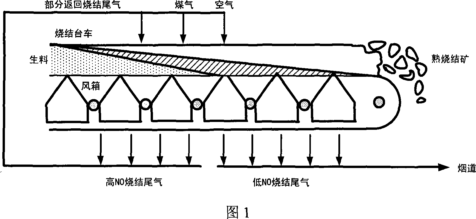
Image

Examples
example 1
[0024] In a small vertical Al 2 o 3 In a straight tube heating furnace, under an inert atmosphere, the single-component gas in the simulated coal gas reduces the NO in the sintering tail gas, and the N 2 The mixed gas of NO and NO simulates the sintering tail gas. The total gas flow rate is 2.5L / min, the concentration of NO is 300ppm, and the gas single-component H 2 , CO and NH 3 The concentration of NO is 0.3%. The heating process of the heating furnace is controlled by the temperature controller, and the concentration of NO in the gas is detected online by the flue gas analyzer. Three gases reduced NO to N when the temperature was raised to 1000 °C in a simulated heating furnace 2 The conversion rates were: 93.5%, 41.7% and 90.3%. When the reaction temperature is kept constant at 1000°C, the concentration of CO is increased to 3.0%, and NO is converted into N 2 The conversion rate can reach 80.8%.
example 2
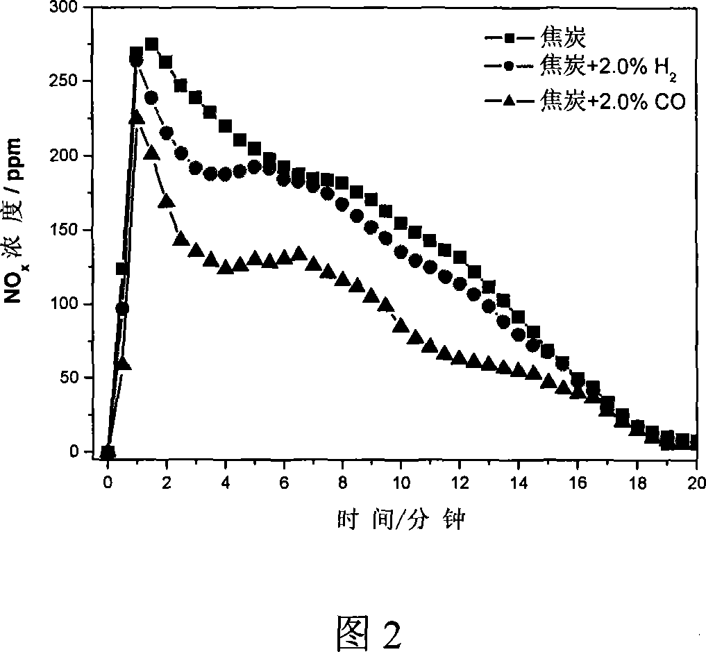
[0026] To simulate the distribution of coke during the sintering process, mix 5g of coke and 50g of alumina pellets evenly and place them in a vertical Al 2 o 3 In the middle of the constant temperature zone of the straight tube heating furnace, the temperature is programmed for heating, and N 2 As a protective gas, when the temperature of the material layer reaches 800°C, switch between air, air and CO mixture or air and H 2 Mixed gas, the total gas flow is 4.0L / min, CO and H 2 The concentration is 2.0%. The result of the reaction is shown in FIG. 2 . In the process of coke combustion, reducing gas H is introduced 2 and CO can effectively reduce NO x The emission concentration of CO2 is more obvious.
example 3
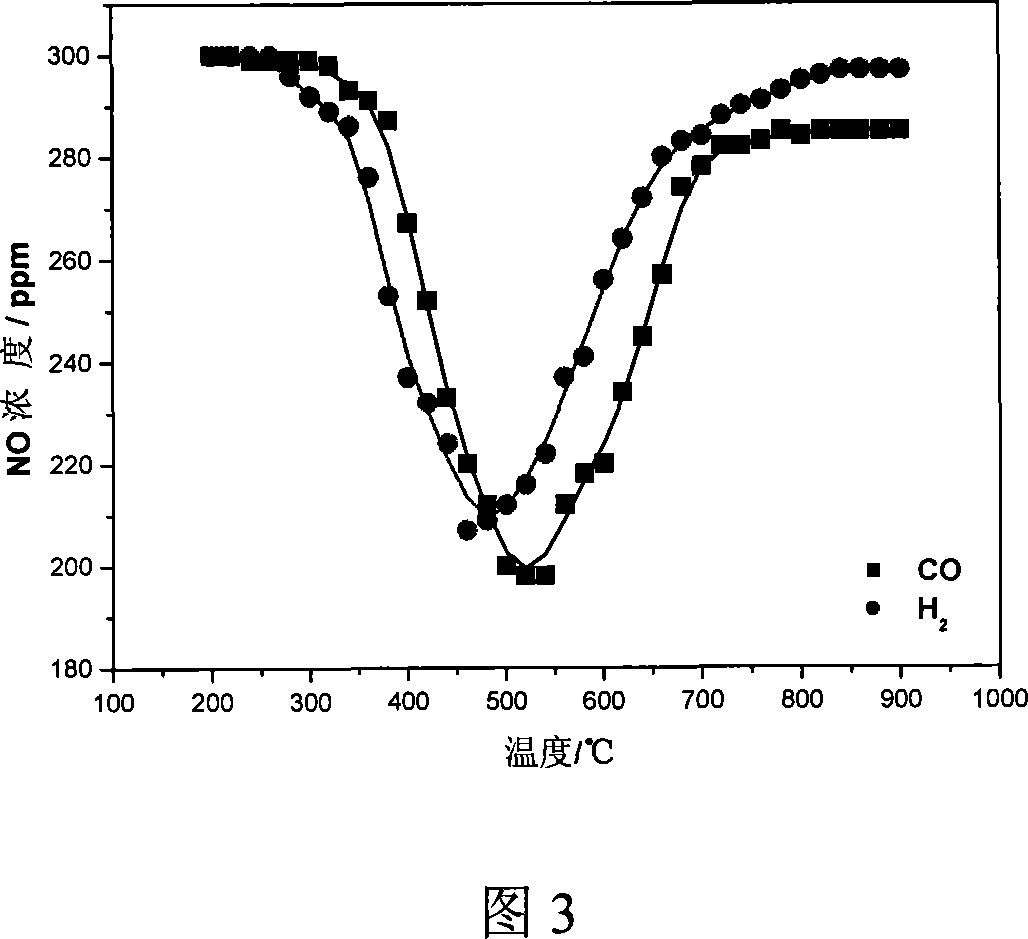
[0028] In a small vertical Al 2 o 3 In the straight tube heating furnace, a certain amount of sintered ore (10 cm in height) is loaded, and the mixed gas of air and NO is used to simulate the returning sintering tail gas, and the NO x The concentration is 300ppm. Heating by temperature programming, CO and H were respectively introduced during the heating process. 2 , to examine the effect of temperature on H 2 and CO to remove NO from combustion tail gas x impact of changes. The flow rate of air is 2.5L / min, CO and H 2 The concentration is 2.0%, under the action of sinter, H 2 and CO removal back to NO in the burnt tail gas x The change law with the reaction temperature is shown in Fig. 3.
[0029] It can be seen from Figure 3 that the sintering tail gas is returned to the sintering process, so that the sintering tail gas passes through the sinter layer, and in the temperature range of about 500 °C, H 2 and CO can convert the NO in the combustion tail gas x The conce...
PUM
 Abstract
Description
Claims
Application Information