Method and device for producing sponge iron by using reducing gas prepared from coke oven gas

A technology of sponge iron and coke oven gas, which is applied in the direction of reducing gas emissions, and can solve problems such as uneconomical production, impossibility of production, and non-compliance with environmental protection requirements

Inactive Publication Date: 2008-01-09
张文慧 +1
View PDF6 Cites 30 Cited by
  • Summary
  • Abstract
  • Description
  • Claims
  • Application Information

AI Technical Summary

Problems solved by technology

However, the organic sulfur in the coke oven gas and the hydrogen sulfide generated when the reducing gas reduces iron ore are not removed. The total sulfur content in these gases is far greater than the maximum sulfur content of 0.1ppm required by the catalyst during natural gas conversion, which will lead to The methane conversion catalyst in the process is rapidly deactivated, which makes the production uneconomical. In the plan for removing carbon dioxide in the tail gas of the reduction reaction, it is only recorded that carbon dioxide can be effectively removed by chemical absorption or physical absorption, and there is no explanation for the removal of carbon dioxide. How to deal with a large amount of hydroge...

Method used


Image

  • Method and device for producing sponge iron by using reducing gas prepared from coke oven gas
  • Method and device for producing sponge iron by using reducing gas prepared from coke oven gas

Examples


Embodiment 1

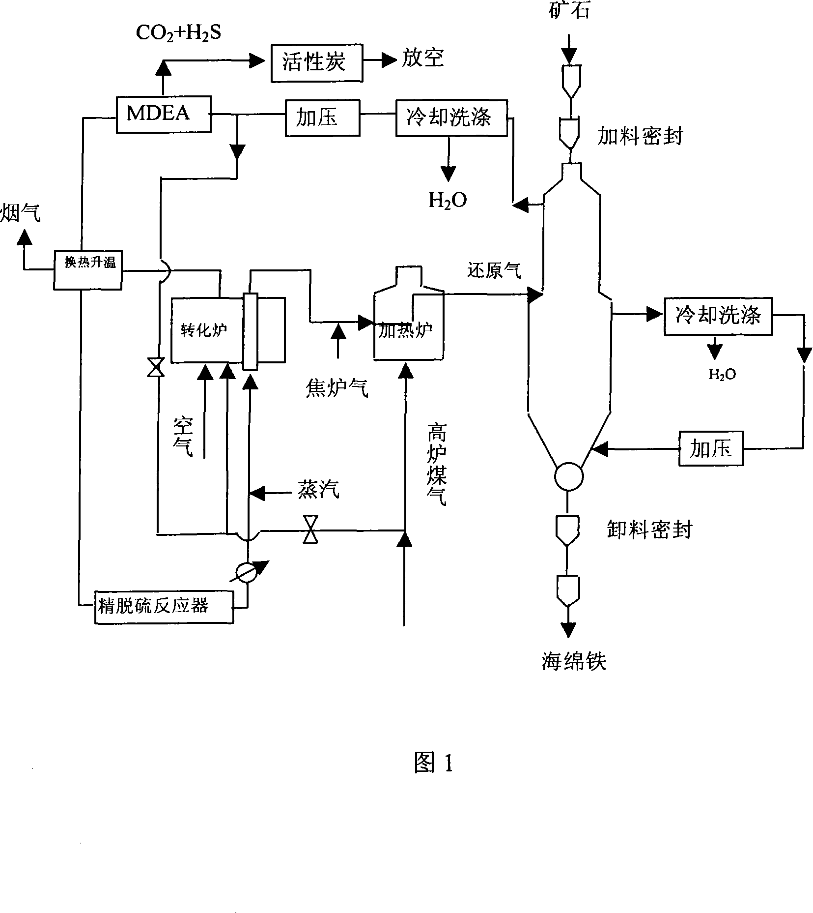
[0035] The coke oven gas is mixed with the reduction tail gas from the methane conversion furnace and enters the heating furnace. After being heated by the blast furnace gas to a temperature above 800°C, it enters the reduction zone of the moving bed reduction reactor. The complex organic sulfur in the coke oven gas is released in the reduction reactor. Most of it is converted into hydrogen sulfide or absorbed by DRI. After cooling, dedusting and dehydration, the reduction tail gas is pressurized to 0.5Mpa, and enters the MDEA section to remove CO in the reduction tail gas. 2 and H 2 S and other acid gas, the released acid gas is removed by activated carbon desulfurizer to remove H 2 After S, it is emptied, and the purified reducing tail gas is preheated to 200°C by the reformer flue gas, and then enters the renewable conversion and absorption type fine desulfurization bed to remove the total sulfur to below 0.1ppm. The activity of the renewable conversion and absorption type ...

Embodiment 2

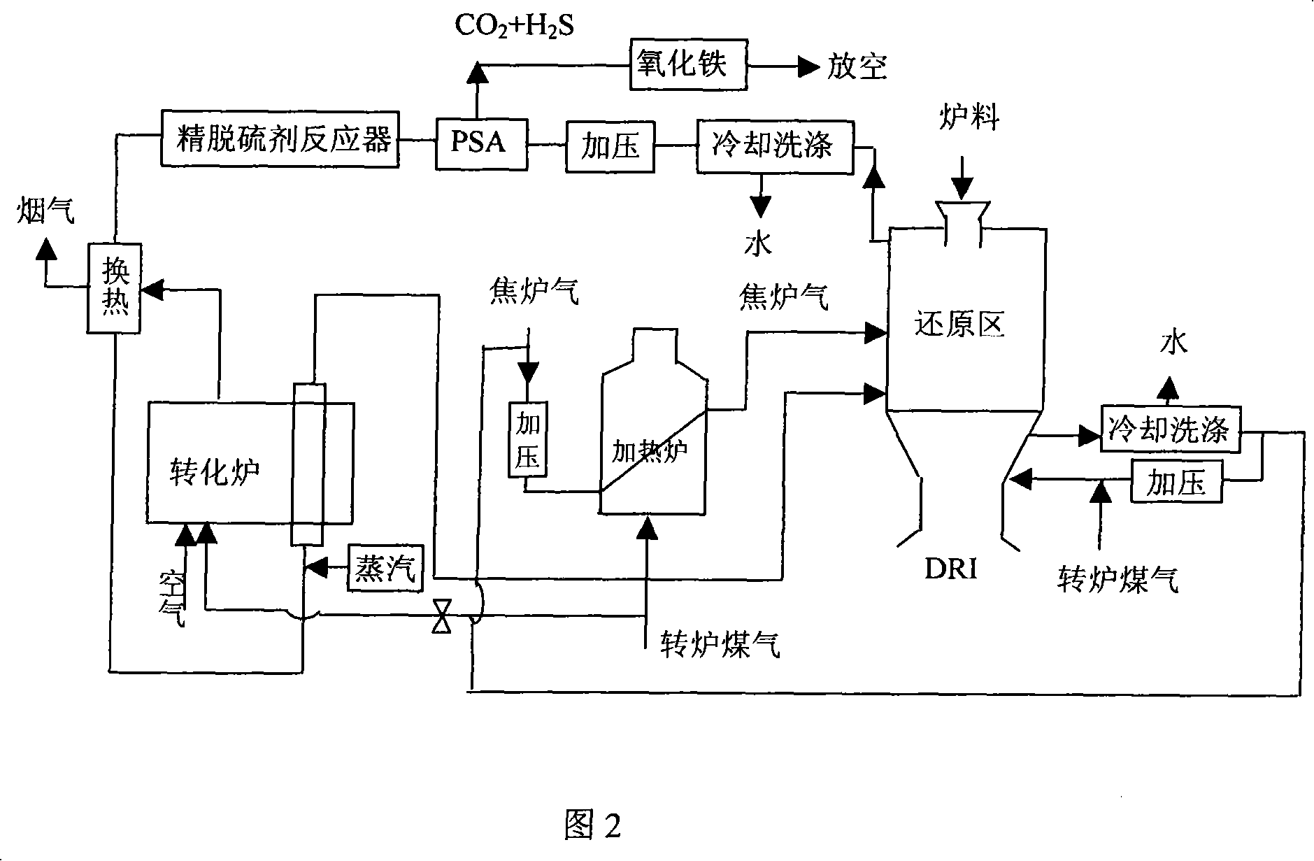
[0037] The reduction tail gas from the upper reduction zone of the DRI moving bed reactor is cooled, dedusted and dehydrated, then pressurized to 0.8Mpa, enters the PSA device, and removes CO 2 、H 2 S and N 2 , the acid tail gas is vented after removing hydrogen sulfide with iron oxide desulfurizer, and the purified reduction tail gas enters the zinc oxide fine desulfurization reactor to remove the total sulfur to below 0.1ppm, and then enters methane steam reforming after heat exchange and heating of flue gas and adding steam Furnace, control steam / gas ratio 0.3:1, reformer outlet temperature 870°C, methane steam reforming catalyst Ni / α-Al 2 o 3 (Z412 / Z413 produced by the Research Institute of Qilu Petrochemical Company); the outlet methane content is less than 1%, and the reduced tail gas after conversion directly enters the moving bed DRI reduction furnace, and its position is higher than the position where the converted reduction gas enters the reduction furnace, so that...


PUM


Abstract

An invention relates to production of sponge iron by using coke oven gas directly, carried out by: mixing purified blast furnace gas with converter gas and blast-furnace gas and one or two kinds of reduced off-gas as well, feeding into upper reduction zone of reactor of vertical shifting bed to reduce ores containing iron oxide, discharging after cooling down in cooling zone of a reduction furnace. End gas is treated by cooling, removing dust, dewatering and pressuring, separating acid gases and inert gases, and then de-sulfurizing, heating in a heat exchanging section to be fed into methane inverting section, feeding the inverted gas to the upper reduction zone said above. An apparatus concerned with the said process is involved. End gas can be used effectively to produce sponge iron at low cost and eliminate sulfur pollution. Methane inverting catalyst can be used durably.

Description

technical field [0001] The present invention relates to a kind of method (DRI) that utilizes coke oven gas to produce synthetic reducing gas, and utilizes direct reducing gas-based method to produce sponge iron, more specifically, relates to a kind of method of coke oven gas producing reducing gas to produce sponge iron and its equipment. Background technique [0002] Direct reduced iron (DRI), also known as sponge iron, is a kind of metallic iron obtained without blast furnace smelting. The process of producing DRI is called non-blast furnace ironmaking process. The production process of DRI is divided into two types: coal-based and gas-based. Among them, the gas-based method currently accounts for 90% of the output of DRI. The typical processes are the tank method (HYL method) and the shaft furnace method (Midrex method). The shaft furnace method uses a vertical moving bed reduction reactor, which is mainly divided into two parts: Reduction zone, where reducing gas circu...

Claims


Application Information

Patent Timeline
IPC IPC(8): C21B13/00
CPCY02P10/143
Inventor 周红军张文慧
Owner 张文慧
Why Eureka
Try Eureka