A manufacturing method of machinery parts for linear motion and linear bushing manufactured by the above method

A manufacturing method and flange technology, which can be applied to manufacturing tools, laser welding equipment, edge parts of workpieces, etc., can solve the problems of dimensional deviation, difficult automatic processing, and reduce the strength of the base metal, so as to strengthen the welding part and reduce the production cost. , the effect of good welding performance

Active Publication Date: 2008-01-23
SAMICK PRECISION IND
View PDF2 Cites 5 Cited by
  • Summary
  • Abstract
  • Description
  • Claims
  • Application Information

AI Technical Summary

Problems solved by technology

Brazing is one of the most common methods used in metal joining, but the problem with brazing is that it degrades the base due to deformation of the material and decarburization during the brazing process due to the high temperatures required for the copper melt to flow. Increase the strength of the base metal, reduce surface hardness, and increase brittleness
In addition, the bonding method has many problems due to difficulty in controlling proper surface roughness, dimensional tolerance, maintenance of a clean surface, and environmental pollution due to bonding materials
The problem with the method of threading the outer casing and flange is that it is expensive to machine because of the high precision that must be done in the process, and the screw joint

Method used


Image

  • A manufacturing method of machinery parts for linear motion and linear bushing manufactured by the above method
  • A manufacturing method of machinery parts for linear motion and linear bushing manufactured by the above method
  • A manufacturing method of machinery parts for linear motion and linear bushing manufactured by the above method

Examples


no. 1 approach

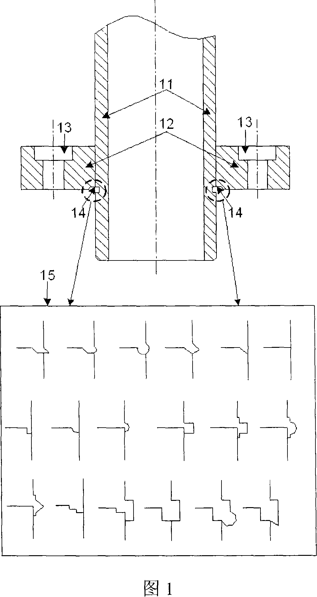
[0040] A first preferred embodiment of the present invention relates to a method of manufacturing a flanged linear bush by machining the inner edge of the flange using a high energy beam with better linearity. Said method for manufacturing a flanged linear bushing comprises the steps of: a) machining the inner side edge of the flange to be connected with the outer sleeve along the inner circumference of said flange for easy connection and better welding, Also facilitates the elimination of interference between the protruding fused and welded surfaces of the flanged linear bushing and the datum plane of the applied base when installed with the applied base; b) at right angles between the flange plane and the axis of the outer sleeve, mechanically connecting the outer sleeve to the machined flange; and c) welding the inner edge of the machined flange and the connecting portion of the outer sleeve using a high-energy beam with better linearity.

no. 2 approach

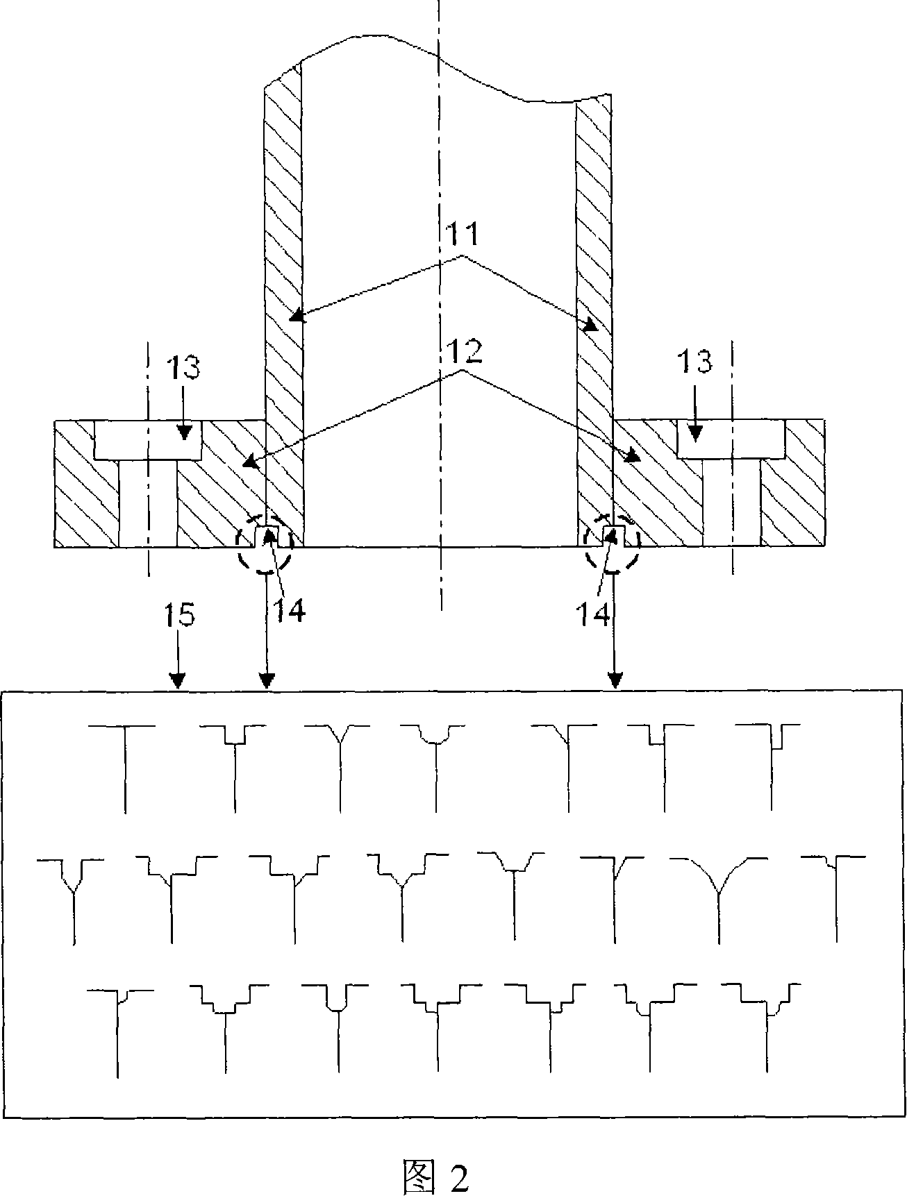
[0042] A second preferred embodiment of the present invention relates to a method for manufacturing a flanged linear bushing, which method includes forming different structures so that the outer sleeve and the flange are easily mechanically connected and welded to each other; and after precise connection A step of welding the connecting portion using a high energy beam. Specifically, the method of manufacturing a flanged linear bushing includes the following steps: a) processing the edge of the outer sleeve at a predetermined angle so that the outer sleeve is mechanically connected to the flange smoothly; b) taking into account the outer sleeve The thickness of the outer sleeve is formed on the outer surface of the predetermined depth and width of the recess to allow a high-energy beam (laser or electron beam) with better linearity to easily enter, and to allow good after the flange is connected to the outer sleeve c) machining the inner edge of the flange along the inner circ...

no. 3 approach

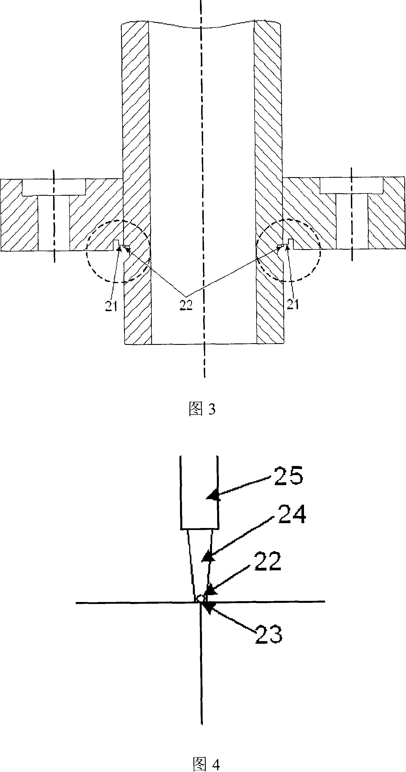
[0045] A third preferred embodiment of the present invention relates to a method of manufacturing a flanged linear bushing using a filler metal to prevent defects in the welded portion and to provide high-quality welding of the connected portion because the filler metal and the connected portion The materials co-melt and infiltrate the weld between the flange and the outer sleeve, which are made of materials with different compositions become.

[0046] A method of manufacturing a flanged linear bushing using a filler metal will be described in more detail. After step b) of the first embodiment, the method of manufacturing a flanged linear bushing using a filler metal in a first preferred embodiment further includes the step of: c) placing a filler metal made of an alloy and having a predetermined diameter in The position between the flange and the outer casing immediately adjacent to the joint 23; and d) using a high-energy beam (laser or electron beam) with good linearity, t...


PUM


Abstract

Disclosed are a flanged linear bushing formed by connecting an outer sleeve and a flange and a method of manufacturing the same. The manufacturing method includes the steps of: processing the edge of the outer sleeve at a predetermined angle to smoothly connect between the flange and the outer sleeve; after the flange and the outer sleeve are connected to each other, taking into account the the thickness of the outer sleeve, forming recesses on the outer surface of said outer sleeve at a uniform depth and width for simple laser welding; in a form corresponding to the recesses formed on said outer sleeve, machining the inner edge of the flange along the inner circumference of the flange to allow simple laser welding; connecting said flange and the outer sleeve manufactured through the above steps; and welding the notch formed on the outer sleeve using a high-energy beam A connection portion that is connected to each other with a structure formed on the flange, or the connection portion is welded with a high-energy beam having better linearity, while feeding a filler metal of a predetermined diameter to the connection at a predetermined speed. The invention can improve productivity through automatic processing, obtain dimensional stability and higher precision, and reduce manufacturing cost by reducing manufacturing processes.

Description

technical field [0001] The present invention relates to a method of manufacturing a flanged linear bushing, and a flanged linear bushing manufactured by the method, the method comprising: processing the edge of the outer sleeve at a predetermined angle, so as to be connected between the flange and the flanged linear bushing. smooth connection between the outer casings; connecting the flange and the outer casing; welding the connecting portion by a high energy beam, or welding the connecting portion by a high energy beam with better linearity, while supplying filler metal to the weld. Background technique [0002] The manufacture of flanged linear bushings usually adopts cold forging method, brazing method, bonding method, shrink fit method, method of screwing the outer casing and flange, wedge and nut assembly method, and snap ring fixing method. Due to the complex manufacturing process, the cold forging method has more problems. If a uniform and stable structure cannot be ...

Claims


Application Information

Patent Timeline
IPC IPC(8): B23P13/00B23K26/00B23K33/00B23P15/00
CPCB23K33/006B23K26/28B23P13/00B23K26/21B23P15/00
Inventor 陈文英赵忠来赵东显金根永
Owner SAMICK PRECISION IND
Why Eureka
Try Eureka