Optical coating film thickness monitoring automatic control system and monitoring method

An automatic control system, optical coating technology, applied in control/adjustment system, non-electric variable control, optics, etc., can solve the problems of high manufacturing cost, poor stability and accuracy, poor film thickness monitoring effect, etc. Stability and accuracy, guaranteed test accuracy, easy installation method

Active Publication Date: 2008-04-16
HENAN COSTAR GRP CO LTD
View PDF0 Cites 20 Cited by
  • Summary
  • Abstract
  • Description
  • Claims
  • Application Information

AI Technical Summary

Problems solved by technology

[0002] Existing film thickness gauges are usually analog, without computer processing functions, poor stability and accuracy, not suitable for continuous multi-layer coating
Can not meet the requirements of high-precision coating
In addition, the adjustment of the optical axis of the existing film thickness gauge is very complicated, and it takes a lot of time for the user or the debugger
In addition, the existing film thickness gauge also has the following defects: 1. The light source emitting part usually adopts a halogen tungsten bulb, or a plane or curved reflector is placed behind the halogen tungsten bulb to enhance the brightness of the emitted light
Since the light emitted by the halogen tungsten lamp itself is relatively weak, and the light emitted by the light source in the direction of the exit aperture is scattered light or parallel light generated by reflection, and the light beam transmitted through the exit aperture is very small, most of the light is projected to the light source. The box wall is wasted in vain, so the utilization rate of light energy is low, and the emitted light is too weak, which leads to weak light signal of the monitoring system, difficulty in monitoring and identification, and poor effect
[0003] 2. The light source lamp is directly connected to the power supply. The fluctuation of the power supply voltage causes the brightness of the light source to be unstable, which affects the accuracy of optical signal monitoring, resulting in poor film thickness monitoring effect
[0004] 3. The heat dissipation measures in the light source box are not effective. The continuous operation of the bulb for a long time will cause the temperature of the light source box to be too high, which will increase the impedance of the power supply and affect the luminous effect of the bulb.
[0005] 4. The luminous performance of the tungsten-halogen bulbs used will be significantly reduced at the end of their service life, which will directly affect the signal quality of the monitoring system, so they must be replaced in time, but relying on manual operation memory, it is impossible to timely and accurately control the replacement time, and its reliability is poor
[0006] 5. The modulator used to modulate light waves usually uses an operational amplifier 1 synchronous motor as the rotational power of the modulation disc, and the rotation speed stability is poor, resulting in uneven wavelength and frequency of the modulated beam, which affects and reduces the monitoring accuracy of the optical signal and monitoring effect
Secondly, the optical holes on the modulation disc are mostly circular or fan-shaped, so that the modulated light wave is an approximate triangular wave curve, and its peak value is filtered to generate high-order harmonics, which makes the signal fluctuate and brings difficulties to signal monitoring.
[0007] 6. The condensing position of the condensing lens in the condensing mirror box is fixed but not adjustable. When the transmitted light changes with different coating machines or installation positions, the focal length and magnification of the lens cannot be adjusted, so that the projected The light spot on the comparison sheet is not uniform, and cannot be completely projected on the comparison sheet, resulting in loss of light energy and attenuation of the optical signal
[0008] 7. When the emitted light beam enters the mirror box, due to the structure in the mirror box, there are many refraction and reflection paths of the light beam, and the optical path is long, resulting in many optical devices, complex structure, and high manufacturing cost.
However, in the prior art, the light-receiving sensor device used in the photoelectric conversion device usually adopts a photomultiplier tube, which has a large volume and takes up a lot of space, and the use of this component must be accompanied by a high-voltage power supply, resulting in complicated circuits and high production costs. high
Secondly, most of the focusing lenses in the receiving optical path of the sensor are fixed installations, so that the projection distance of the focal point of the lens cannot be adjusted. Attenuation, thus affecting the monitoring effect of the entire monitoring system

Method used


Image

  • Optical coating film thickness monitoring automatic control system and monitoring method
  • Optical coating film thickness monitoring automatic control system and monitoring method
  • Optical coating film thickness monitoring automatic control system and monitoring method

Examples


Embodiment Construction

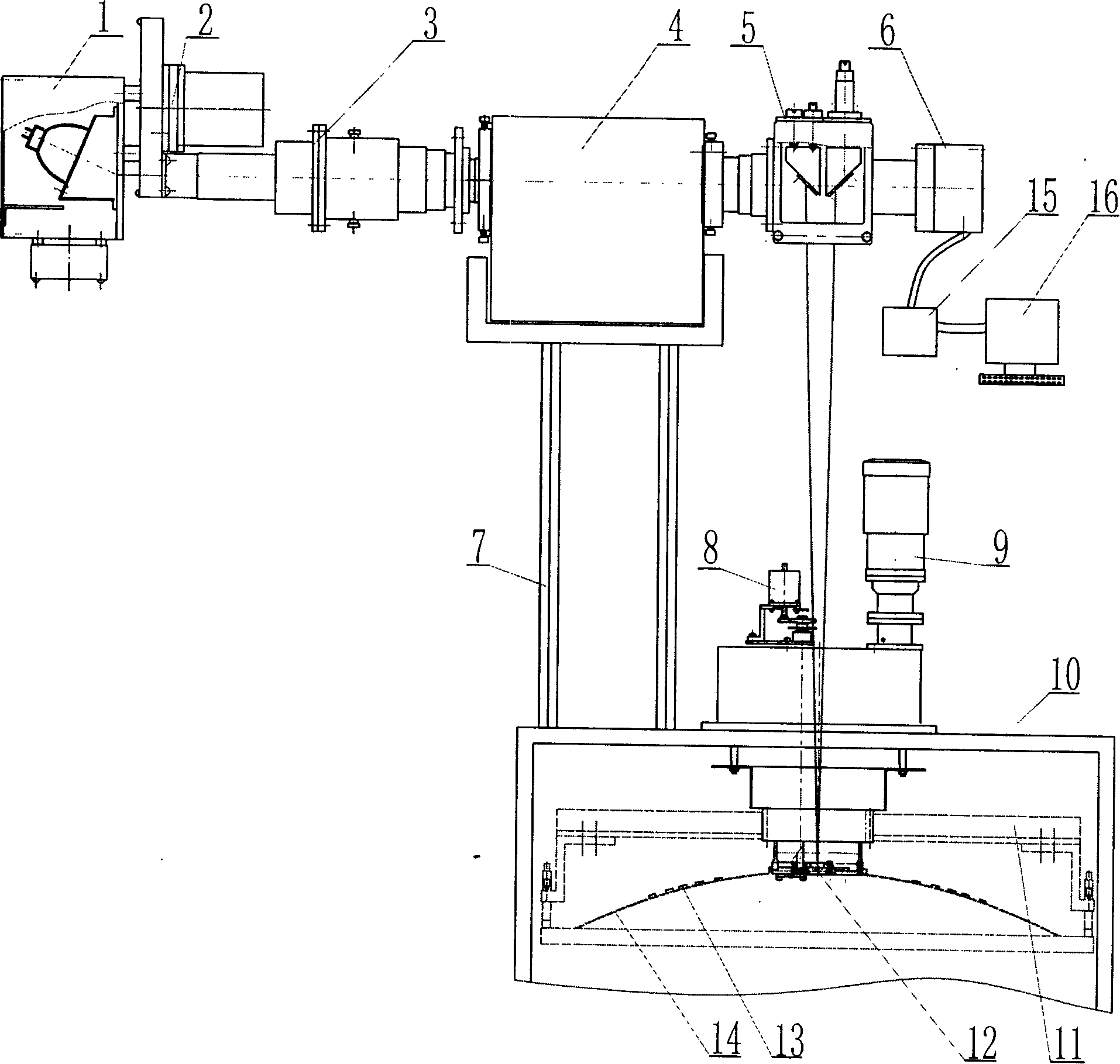
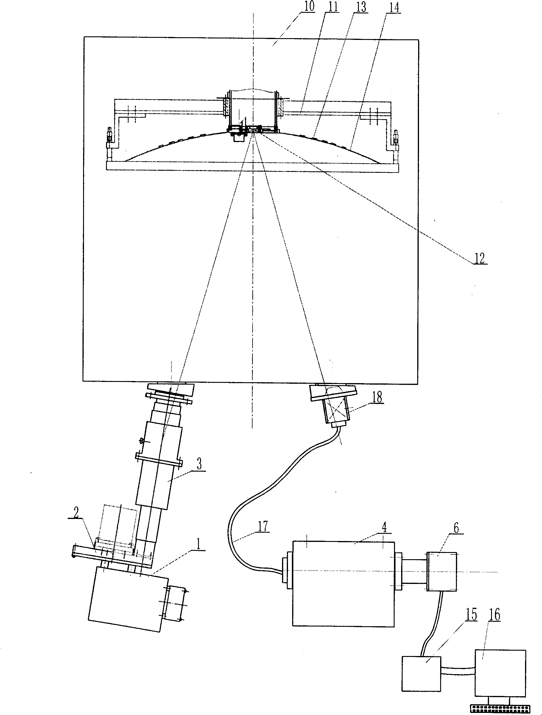
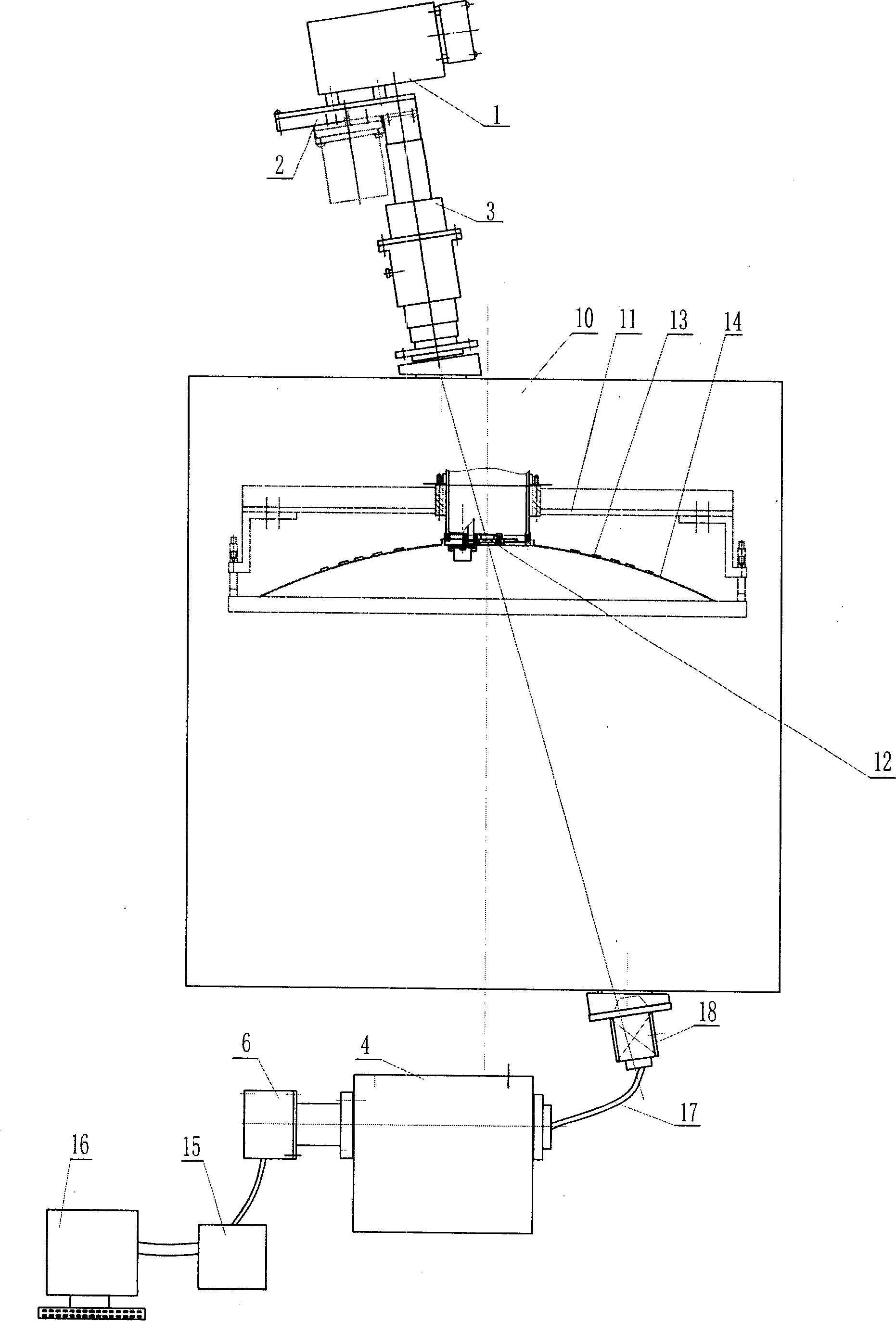
[0050] see figure 1 , the labels in the figure are respectively: light source emission box 1, modulator 2, condenser tube 3, beam splitter 4, mirror box 5, photoelectric signal conversion device 6, connecting bracket 7, comparison plate transposition mechanism 8, working disc rotation Mechanism 9 , evaporation chamber 10 , turntable frame 11 , comparison plate 12 , optical substrate 13 , workpiece turntable 14 , signal processing unit 15 , and computer 16 .

[0051] figure 1 Shown is a schematic diagram of the assembly structure of Embodiment 1 of the present invention, and its film thickness monitoring device adopts an upper-mounted upper reflection optical path, including a light source emission box 1, a modulator 2, a condenser tube 3, a beam splitter 4, a mirror box 5 and The photoelectric signal conversion device 6 is installed on the top of the evaporation chamber of the coating machine after the components are assembled in sequence. During the evaporation monitoring p...


PUM


Abstract

The invention relates to an automatic control system for monitoring the film thickness of optical filming. A light projecting device is directly connected with a light entrance port of a film coating machine or is connected with an optical splitter and a reflector chest for projecting light generated by the light projecting device into the film coating machine, a light exit portal of the film coating machine is connected with a light transporting element which is connected with a light entrance port of the optical splitter, a light exit portal of the optical splitter is further connected with a light entrance port of a photoelectric signal changeover gear, or an exit ray of the film coating machine reflects light into the photoelectric signal changeover gear through the reflector chest, an electrical signal output end of the photoelectric signal changeover gear is connected with a computer through a signal processing unit. The invention further relates to an automatic control method for monitoring the film thickness. The invention improves the stability and accuracy of monitoring the film thickness and meets the requirement of filming with high degree of accuracy.

Description

technical field [0001] The invention belongs to the field of real-time monitoring of optical coatings, in particular to a monitoring control system and an automatic control method for evaporating the surface film thickness of workpieces using optical coatings. Background technique [0002] Existing film thickness gauges are usually analog without computer processing functions, have poor stability and accuracy, and are not suitable for continuous multi-layer coating. Can not meet the requirements of high-precision coating. In addition, the adjustment of the optical axis of the existing film thickness gauge is very complicated, and it takes a lot of time for the user or the adjustment personnel. In addition, the existing film thickness gauge also has the following defects: 1. The light source emitting part usually adopts a halogen tungsten bulb, or a plane or curved reflector is placed behind the halogen tungsten bulb to enhance the brightness of the emitted light. Since the...

Claims


Application Information

Patent Timeline
Patent Type & Authority Applications(China)
IPC IPC(8): C23C14/54G05D5/03G02B26/02
Inventor 菊池和夫赵升林杨育兴张兰党亚军
Owner HENAN COSTAR GRP CO LTD
Why Eureka
Try Eureka