
Electric deionized water manufacturing equipment

A technology for deionized water and manufacturing equipment, applied in ion exchange treatment equipment, ion exchange, ion exchange column/bed method, etc., can solve problems such as poor contact of ion exchange membranes, achieve fast ion movement speed, reduce material costs, The effect of low water resistance

Inactive Publication Date: 2008-07-16
ORGANO CORP
View PDF1 Cites 0 Cited by
  • Summary
  • Abstract
  • Description
  • Claims
  • Application Information

AI Technical Summary

Problems solved by technology

In order to solve the problem of expansion and contraction of such a single ion exchanger, it is also considered to predetermine the volume ratio of the salt form or regeneration form of the ion exchanger filled in the deionization chamber. However, in the electric deionized water production device In continuous operation, the ratio of the salt form or regeneration form of the deionization chamber is determined according to the water quality or current efficiency of the treated water, so it is impossible to predetermine a certain volume and fill it
Under such circumstances, it is desirable to develop an electric deionized water production device that maintains the advantages of the electric deionized water production device using a bulk exchanger described in Japanese Patent Laid-Open No. 2003-334560, And solve the problem of single flow or poor contact with the ion exchange membrane caused by the expansion and contraction of the ion exchange reaction
[0008] Therefore, the object of the present invention is to provide an electric deionized water production device, which has a simple structure, reduces material costs, processing costs and assembly costs, and accelerates the moving speed of adsorbed ionic impurities to facilitate removal of adsorbed ions. , and there will be no problem of single flow or poor contact with the ion exchange membrane caused by expansion and contraction during the ion exchange reaction

Method used

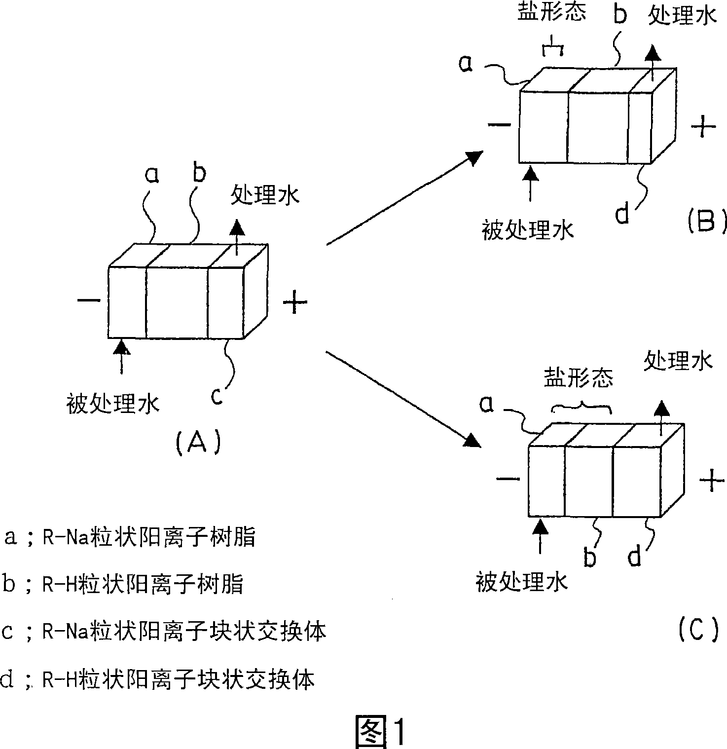
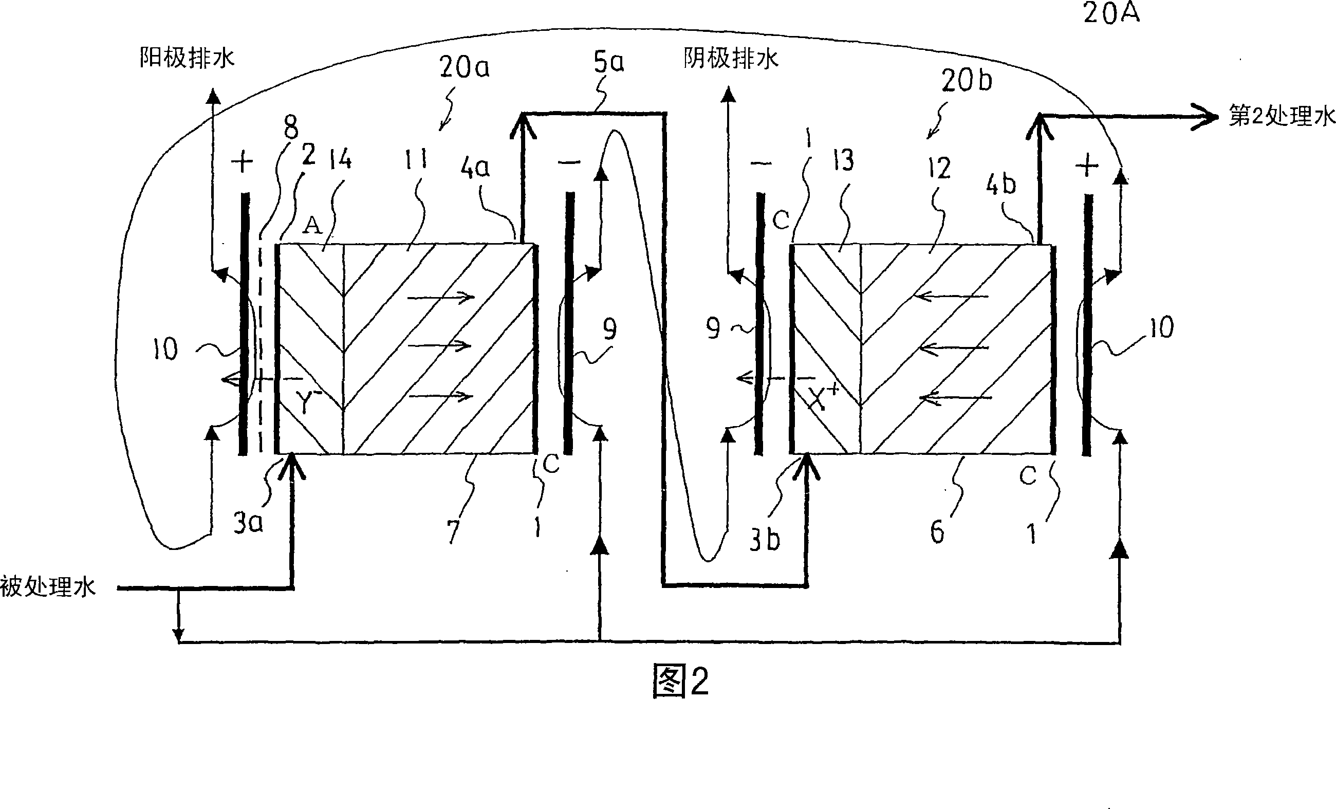
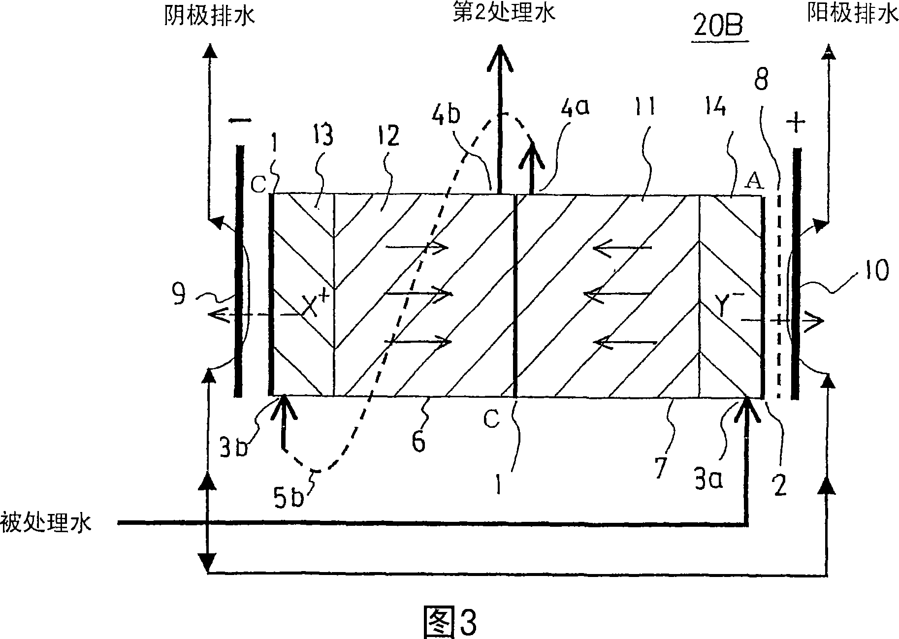

Image

  • Electric deionized water manufacturing equipment
  • Electric deionized water manufacturing equipment
  • Electric deionized water manufacturing equipment

Examples


Embodiment

[0071] Next, the present invention is described in more detail through examples, but the examples are only illustrations of the present invention, and do not limit the present invention.

[0072] (Fabrication of electrical deionized water production equipment)

[0073] An electric deionized water production device of the following specifications shown in the schematic diagram of FIG. 5 was used.

[0074] Tank size: 160mL (length 5cm x width 4cm x height (length between electrodes) 8cm);

[0075] Tank container: internal volume 160mL;

[0076] Anion exchange resin (filled on the anode side): 120mL (IRA402BL), length 5cm x width 4cm x height (length between electrodes) 6cm;

[0077] Cation block exchanger: cut off the block exchange body described in the embodiment of Japanese Patent Application Laid-Open No. 2003-334560 to make a block exchange body of 5 cm in length x 4 cm in width x 2 cm in height;

[0078] ·Water to be treated: Water permeated by reverse osmosis membrane,...


PUM

PropertyMeasurementUnit
diameteraaaaaaaaaa
electrical conductivityaaaaaaaaaa

Abstract

This invention provides an electric deionized water production apparatus in which a direct current field is applied to a deionization chamber filled with an ion exchanger so that ions to be excluded are allowed to migrate in an identical or opposite direction to a water passing direction within the ion exchanger, whereby ionic impurities adsorbed to the ion exchanger are excluded to the outside of the system. The electric deionized water production apparatus is characterized in that the ion exchanger is a mixture of a monolithic organic porous ion exchanger with a particulate ion exchange resin. The electric deionized water production apparatus has a simple apparatus structure, can reduce material cost, process cost, and assembly cost, can accelerate the migration of the adsorbed ionic impurities to facilitate the exclusion of the adsorbed ions and, further, is free from the single flow by swelling or shrinkage involved in an ion exchange reaction, or a failure of contact with an ion exchange membrane.

Description

technical field [0001] The present invention relates to an electric deionized water manufacturing device, which is used in various industries such as semiconductor manufacturing industry, pharmaceutical industry, food industry, power plant, research institute, etc. or sugar liquid, fruit juice, wine, etc. using deionized water. Manufacturing etc. Background technique [0002] As a method for producing deionized water, there is a conventionally well-known method in which water to be treated is passed through a granular ion exchange resin (hereinafter, also simply referred to as "ion exchange resin") to deionize it. However, In this method, when the ion-exchange capacity of the ion-exchange resin decreases, it needs to be regenerated with chemicals. In order to solve the disadvantages of this treatment operation, a deionized water production method using an electrical deionization method has been established and implemented. Practical, this method does not require regeneratio...

Claims


Application Information

Patent Timeline
Patent Type & Authority Applications(China)
IPC IPC(8): C02F1/469B01D61/48B01J47/00
CPCB01J47/08B01D61/485C02F2201/46115B01J47/007C02F1/4695C02F2201/4617B01D61/48C02F2201/4611C02F1/441B01J20/28042C02F5/00B01J47/018
Inventor 田岛直幸山中弘次井上洋中村彰
Owner ORGANO CORP
Learn More