
Method of removing PM2.5 and gaseous pollutant using steam phase transition and device thereof

A technology for PM2.5 and pollutants, applied in chemical instruments and methods, separation methods, and the use of liquid separation agents, etc., can solve the problems of large environmental hazards, fine dust particle size, and low capture rate of PM2.5

Inactive Publication Date: 2008-07-23
SOUTHEAST UNIV
View PDF0 Cites 28 Cited by
  • Summary
  • Abstract
  • Description
  • Claims
  • Application Information

AI Technical Summary

Problems solved by technology

The main pollutants in the flue gas of fuel oil and natural gas boilers are soot, SO 2 , NO x etc. Due to the low concentration of smoke and dust, it has not yet attracted enough attention. The removal of gaseous pollutants mainly includes wet and dry methods. 2.5 The concentration is equivalent to that of coal-burning flue gas, and it is rich in organic components, which is more harmful to the environment
The pollutants in the flue gas of solid waste incineration such as garbage and sludge mainly include dust, heavy metals and SO 2 , HCl, HF, NO x Such as acidic gaseous pollutants, dust removal mainly uses bag filter and electrostatic precipitator, although the dust removal efficiency can be higher than 99%, but for PM 2.5 The capture rate is not high, SO 2 The removal of gaseous pollutants such as , HCl, and HF mainly includes three methods: wet method, dry method, and semi-dry method. Heavy metals such as Cr, Cd, Ni, Pb, Se, etc. are mainly enriched in fine particles, especially PM 2.5 In the process, only by removing the fine particles in the flue gas can the heavy metals be effectively removed
Currently, for the above emission sources, there is no effective PM 2.5 Removal Technology and Cooperative PM Removal 2.5 and gaseous pollutants

Method used


Image

  • Method of removing PM2.5 and gaseous pollutant using steam phase transition and device thereof
  • Method of removing PM2.5 and gaseous pollutant using steam phase transition and device thereof

Examples


Embodiment 1

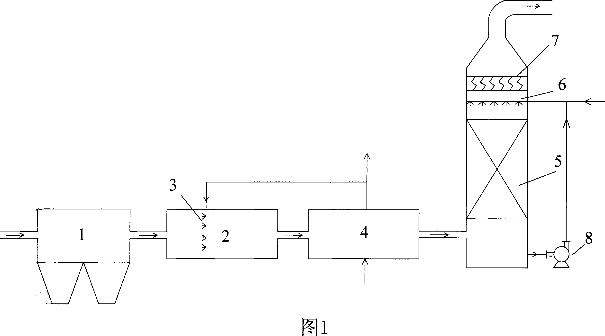
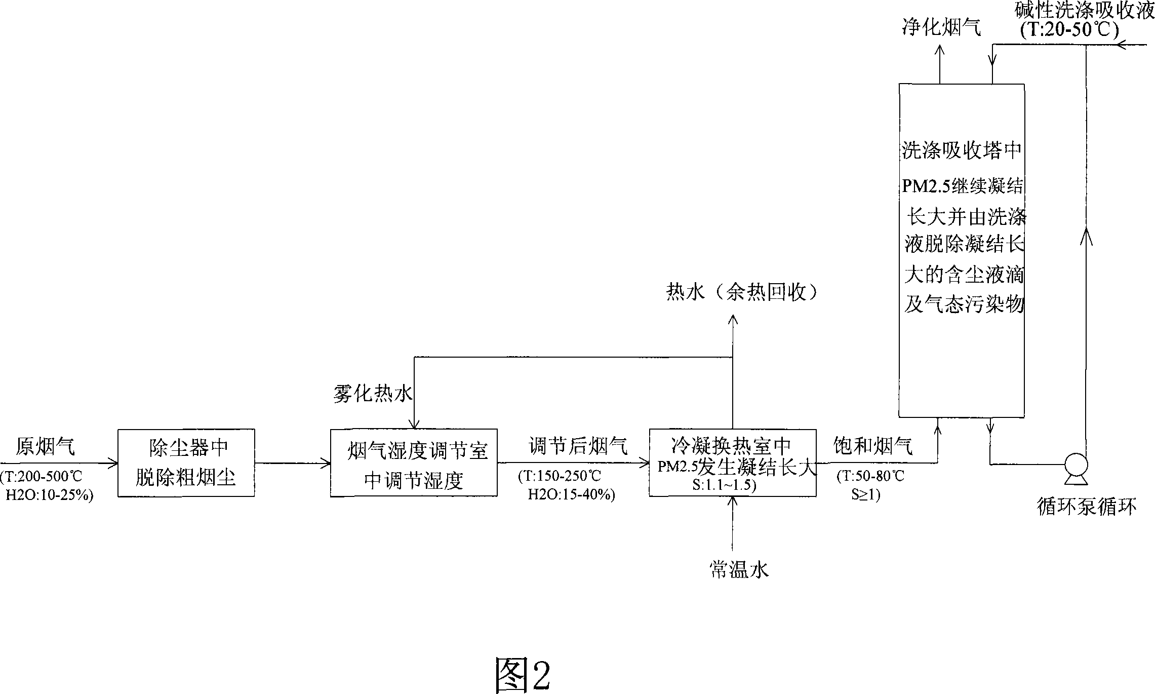
[0019] The flue gas is produced by a fully automatic oil-fired boiler with a flue gas volume of 65Nm 3 / h, the water vapor content in the flue gas is 12%, the exhaust gas temperature is 282°C, the peak particle size of the smoke dust concentration is 0.07μm, most of which are between 0.03~0.5μm, SO in the flue gas 2 The concentration is 624mg / Nm 3 The wet scrubber adopts a spray tower with a diameter of 150mm and a tower height of 1500mm. The top of the spray tower is equipped with a wire mesh demister, and the washing absorption liquid is Ca(OH) 2 suspension. The dust-containing flue gas produced by the oil-fired boiler directly enters the humidity control room, and is sprayed by the atomizing nozzle into a fine water mist with a temperature of 70°C and a particle size of 20-30μm, and the spraying amount is per Nm 3 The flue gas is 0.01kg. After adjustment, the water vapor content of the outlet flue gas is increased to 24%, and the temperature is 235℃; then it enters the tube-and...

Embodiment 2

[0021] Except for the following changes, the rest is the same as in Example 1.

[0022] The scrubbing absorption tower adopts a swirling plate tower, with 3 swirling plates built-in, a swirling plate demister is installed on the top, and the washing absorption liquid is Na 2 CO 3 Solution, liquid-gas ratio 3.5L / Nm 3 ; After testing, PM 2.5 The mass concentration removal efficiency is 86%, the number concentration removal efficiency is 72%, and the flue gas desulfurization efficiency is 89%.

Embodiment 3

[0024] The flue gas is produced by garbage incineration, and the flue gas volume is 70Nm 3 / h, water vapor content in flue gas is 21%, temperature is 243℃, SO in flue gas 2 The concentrations of HCl, HF are 729mg / Nm respectively 3 ,876mg / Nm 3 , 21mg / Nm 3 , The peak particle size of the dust concentration at the outlet of the dust collector is 0.7μm, and the number concentration is 10 6 Pcs / cm 3 ; The scrubbing absorption tower is a cyclone plate tower with a tower diameter of 150mm and a tower height of 1500mm, with 3 built-in cyclone plates, and a cyclone plate demister on the top. The scrubbing absorption liquid is Na 2 CO 3 Solution. After the waste incineration flue gas is removed by the cyclone dust collector, it enters the humidity control room, and is sprayed into a fine water mist with a temperature of 65°C and a particle size of 20-30μm from the atomizing nozzle, and the spraying amount is per Nm 3 The flue gas is 0.008kg. After adjustment, the water vapor content in the ...


PUM

PropertyMeasurementUnit
Particle sizeaaaaaaaaaa

Abstract

The invention relates to a method and a device which adopt steam phase changing to cooperatively remove PM2.5 and gas pollutions from a high temperature and high humidity flue gas. The invention comprises a dust catcher, a flue gas humidity regulating chamber, a condensing heat exchanger and a washing absorption tower. The method is that the flue gas enters the flue gas humidity regulating chamber after coarse dust removing in the dust catcher, and atomized hot water is sprayed to regulate the humidity of the flue gas; after humidity regulation, the flue gas is induced into the condensing heat exchanger to reach supersaturation, and the supersaturation steam takes the PM2.5 as condensing core to generate phase changing, thus increasing the granularity of the PM2.5; then the steam enters the washing absorption tower, and in the tower, the flue gas reversely contact a middle-lower temperature alkalescent washing-adsorbing liquid to be further subject to the phase changing of the steam taking PM2.5 as condensing core, and the alkalescent washing-adsorbing is adopted for removing the growing dust-drop and gas pollutions. Taking the characteristics of the high temperature and high humidity flue gas into account, the invention adopts the steam phase changing theory to lead the PM2.5 to be condensed and to grow so as not only to cooperatively remove PM2.5 and gas pollution, but to recycle the gasifying potential heat released by steam condensing and the sensible heat caused by temperature reduction of the flue gas.

Description

1. Technical Field [0001] The invention belongs to PM in flue gas 2.5 The technical field of the removal of particulates and gaseous pollutants, in particular to the application of the principle of steam phase change to synergistically remove PM from flue gas with high temperature and high humidity 2.5 And gaseous pollutants. 2. Background technology [0002] Inhalable particulate matter is currently the primary pollutant of the urban atmospheric environment in my country, especially PM with an aerodynamic diameter less than 2.5μm 2.5 The pollution problem is very serious, mainly due to PM 2.5 The particles have a large specific surface area and are easy to accumulate various heavy metals and chemical carcinogens, but conventional dust removal technology is difficult to effectively capture them, resulting in a large amount of PM 2.5 Discharge into the atmosphere. Burning is caused by PM in the atmosphere 2.5 The main reason for the increase in content is to control the combustion...

Claims


Application Information

Patent Timeline
IPC IPC(8): B01D51/02B01D53/78B01D47/06
Inventor 杨林军张霞颜金培沈湘林
Owner SOUTHEAST UNIV
Learn More