Welding process for high damping copper alloy and steel

A welding process, copper alloy technology, applied in the direction of welding medium, welding equipment, welding equipment, etc., can solve the problems of no patent literature, etc., achieve good fluidity, good noise reduction effect, good air tightness effect

Inactive Publication Date: 2008-08-20
725TH RES INST OF CHINA SHIPBUILDING INDAL CORP
View PDF0 Cites 11 Cited by
  • Summary
  • Abstract
  • Description
  • Claims
  • Application Information

AI Technical Summary

Problems solved by technology

[0007] In the domestic and foreign literature search related to the welding of high damping copper alloy and steel, there is no releva

Method used


Image

  • Welding process for high damping copper alloy and steel
  • Welding process for high damping copper alloy and steel
  • Welding process for high damping copper alloy and steel

Examples


Embodiment 1

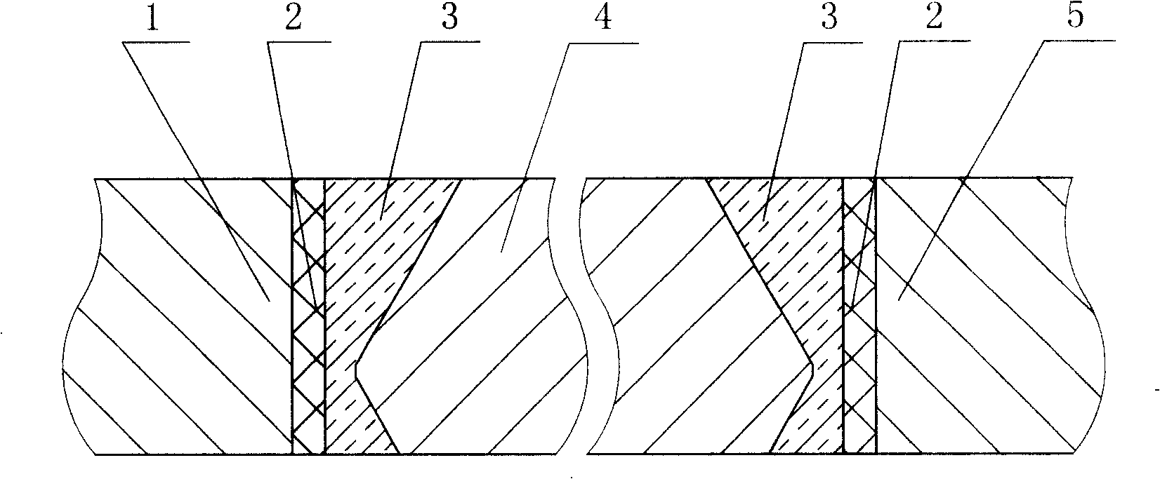
[0026] Take the CuMn50 alloy of the gear web of the marine power system, and the material of the ring gear and the hub is 40CrNiMoA as an example:

[0027] The spoke plate is made of CuMn50 alloy, which mainly uses its high damping characteristics to reduce the noise of gears in the traditional system. figure 1 K-shaped groove, that is, to process the K-shaped groove on the connecting surface of the spoke plate, the ring gear and the hub. The grease, water and other impurities on the surface within 30mm on both sides of the groove, as well as the oxide film on the metal surface must be carefully checked. Clean until a metallic sheen is revealed.

[0028] Using cerium tungsten electrode, DC manual tungsten argon arc welding, the purity of protective argon is ≥99.99%.

[0029] ERNi-1 surfacing welding is used on the connection surface of the gear (ring gear, wheel hub) structural steel, φ2.5mm welding wire, surfacing welding thickness 3mm, welding interlayer temperature ≤ 50 ℃...

Embodiment 2

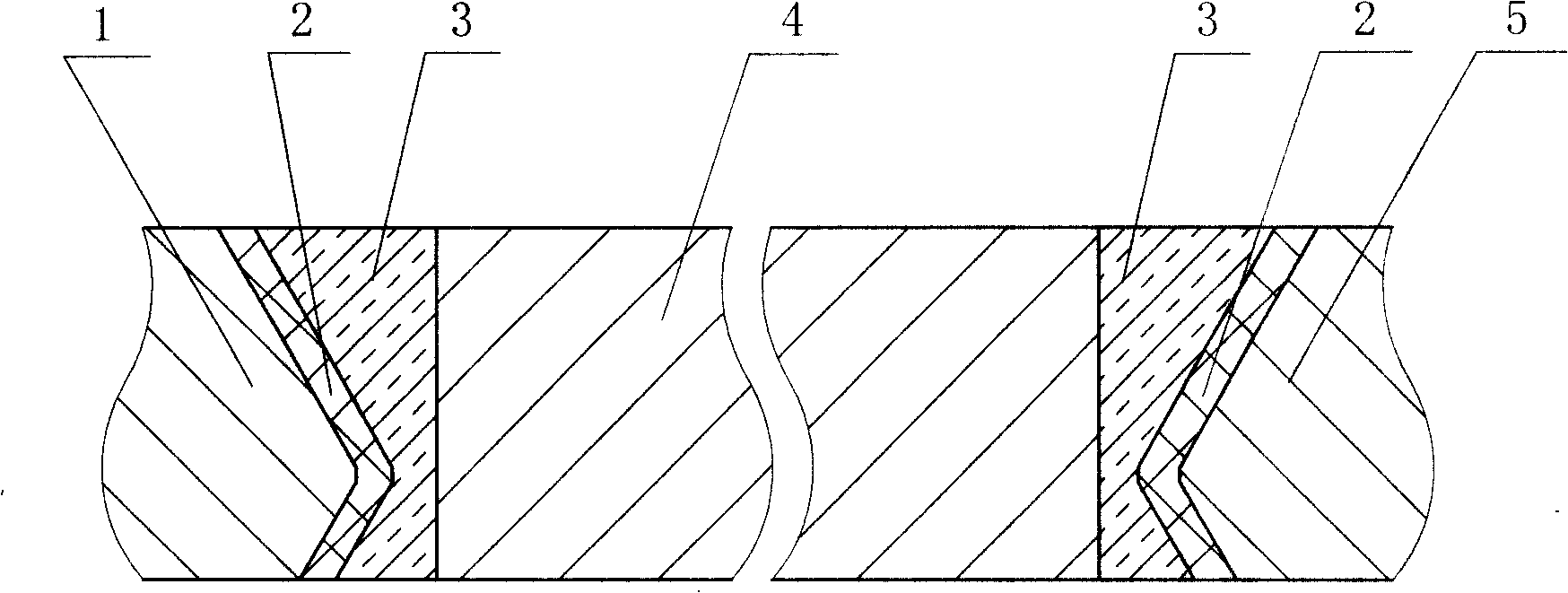
[0036] CuMn50 alloy is used for the gear web, and the groove type is as follows figure 2 As shown, the ring gear and hub are made of alloy steel 30CrMoA as an example:

[0037] Using the same welding process as described in Example 1, 25mm thick CuMn50 and 30CrMoA welded joint performance: normal temperature tensile strength (R m / MPa)460~500; impact energy (A Kv / J) 100~110; cold bending angle (d=4a) 65°~80°. Weld fatigue life 10 7 Under the conditions, the stress is greater than 100MPa. All meet the target requirements.

Embodiment 3

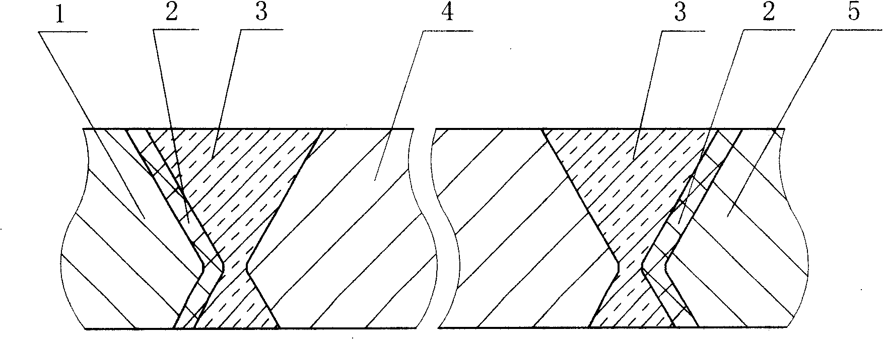
[0039] CuMn50 alloy is used for the gear web, and the groove type is as follows image 3 As shown, the ring gear and hub are made of alloy steel 20CrMnMo as an example:

[0040] Using the same welding process as described in Example 1, 25mm thick CuMn50 and 20CrMnMo welded joint performance: normal temperature tensile strength (R m / MPa)460~500; impact energy (A Kv / J) 90~110; cold bending angle (d=4a) 60°~80°. All met the required indicators.


PUM

PropertyMeasurementUnit
Stressaaaaaaaaaa

Abstract

The invention relates to a welding procedure between high-damp copper alloy and steel, belonging to the metal material welding field. The procedure adopts the method of argon tungsten-arc welding; a K-shaped or an X-shaped groove is arranged on the welding surface of the high-damp copper alloy and the steel, namely the K-shaped groove is arranged on the connecting surface of either the high-damp copper alloy or the structural steel, or the K-shaped groove is arranged on the connecting surfaces of both the high-damp copper alloy and the structural steel; firstly adopt nickel bare welding filter metal to perform surfacing welding on the structural steel to form a transition layer; and then adopt cupronickel welding wire to perform butt welding on the high-damp copper alloy to realized the connection between the steel and the high-damp copper alloy. The welding procedure has the advantages that the welding problem between the high-damp copper alloy and the steel can be solved with high efficiency and low cost; the mechanical property of the weld joint of the finished welding part is excellent; the invention can be applied on the power transmission system; under the work conditions of low torque and high rotational speed or high torque and low rotational speed, the welding procedure can meet the application requirements; and compared with the original simulating steel part, the noise reduction performance is good.

Description

technical field [0001] The invention belongs to metal material welding, and mainly relates to a welding process between high-damping copper alloy and steel. Background technique [0002] Welding is one of the commonly used processes to realize the connection of metal materials. In parts that do not require special requirements for use, welding of the same metal materials is generally involved, such as welding of steel to steel, copper alloy to copper alloy, etc. However, in occasions with special requirements, such as the power transmission system of large-scale equipment, due to the change of the elastic stiffness of the teeth caused by the meshing of the gears during the transmission process, and the machining error of the teeth, an exciting force is generated, which makes the gear body vibrate, and the sound value is as high as 100dB. above. In this case, it is necessary to use materials with special functions such as damping alloy materials to achieve the purpose of re...

Claims


Application Information

Patent Timeline
IPC IPC(8): B23K9/23B23K35/30B23K9/095B23K33/00B23K9/16B23K35/38B23K103/18
Inventor 雷竹芳何刚王永朝
Owner 725TH RES INST OF CHINA SHIPBUILDING INDAL CORP
Why Eureka
Try Eureka