Rotary type pressure-variable adsorption gas separating method

A technology of pressure swing adsorption and gas separation, which is applied in the separation of mixed gases and the field of rotary pressure swing adsorption gas separation. It can solve the problems of large amount of adsorbent, low production capacity, cumbersome operation, etc., and achieve convenient operation and high equipment production capacity. High, fast absorption effect

Inactive Publication Date: 2008-08-27
刘昂峰
View PDF0 Cites 13 Cited by
  • Summary
  • Abstract
  • Description
  • Claims
  • Application Information

AI Technical Summary

Problems solved by technology

[0003] Obviously, pressure swing adsorption gas separation technology has many shortcomings such as complex equipment, huge investment, cumbersome and unstable operation, large amount of adsorbent, high energy consumption, and low production capacity.

Method used


Image

  • Rotary type pressure-variable adsorption gas separating method
  • Rotary type pressure-variable adsorption gas separating method
  • Rotary type pressure-variable adsorption gas separating method

Examples


Embodiment 1

[0031] Embodiment 1 air separation prepares oxygen and nitrogen

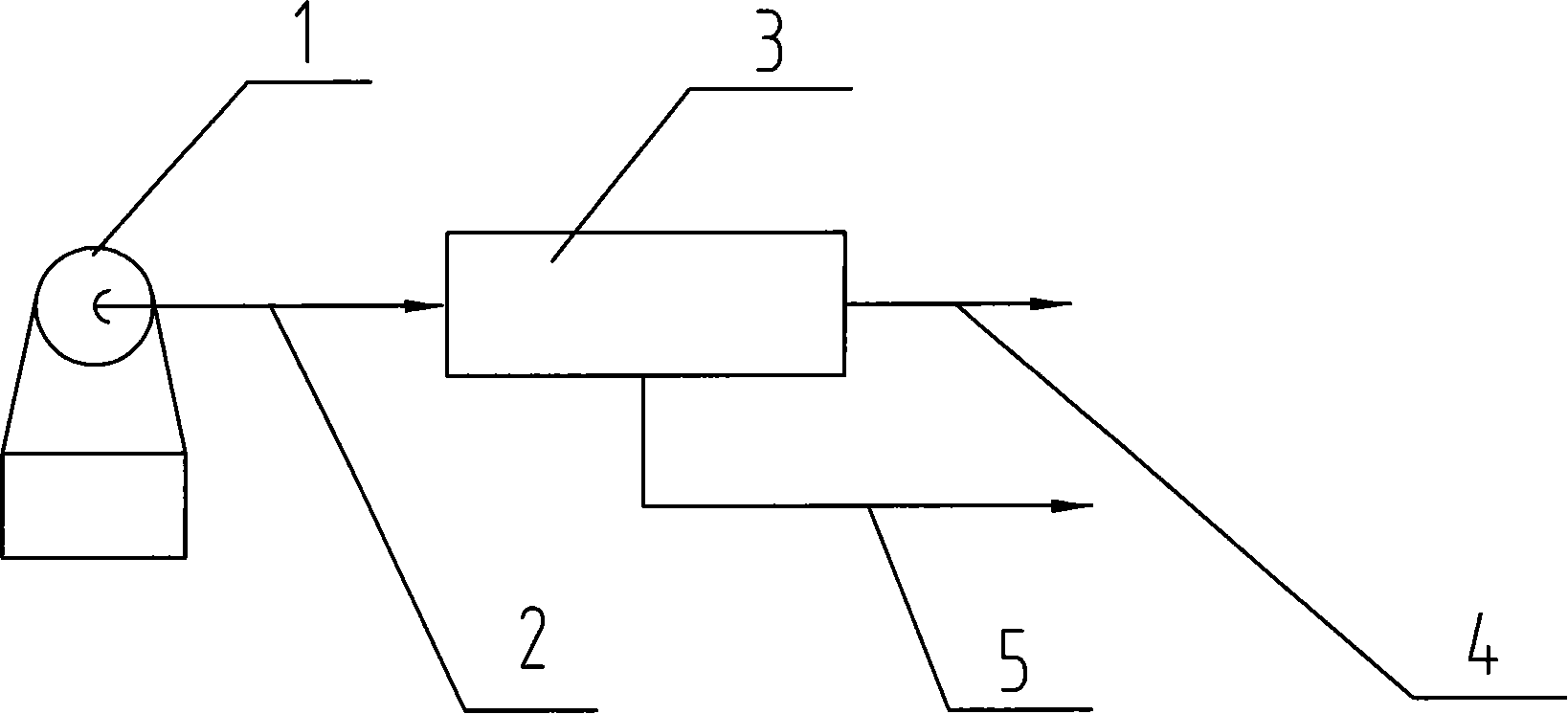
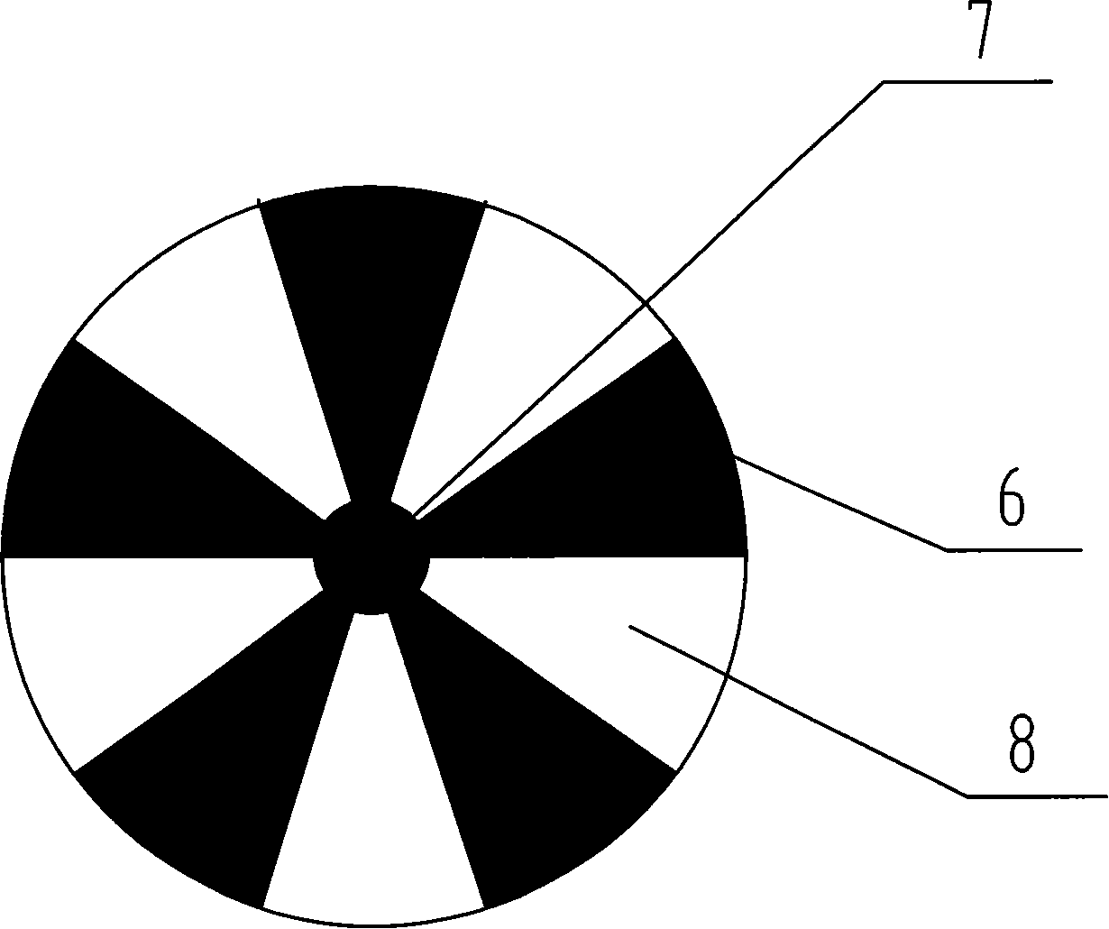
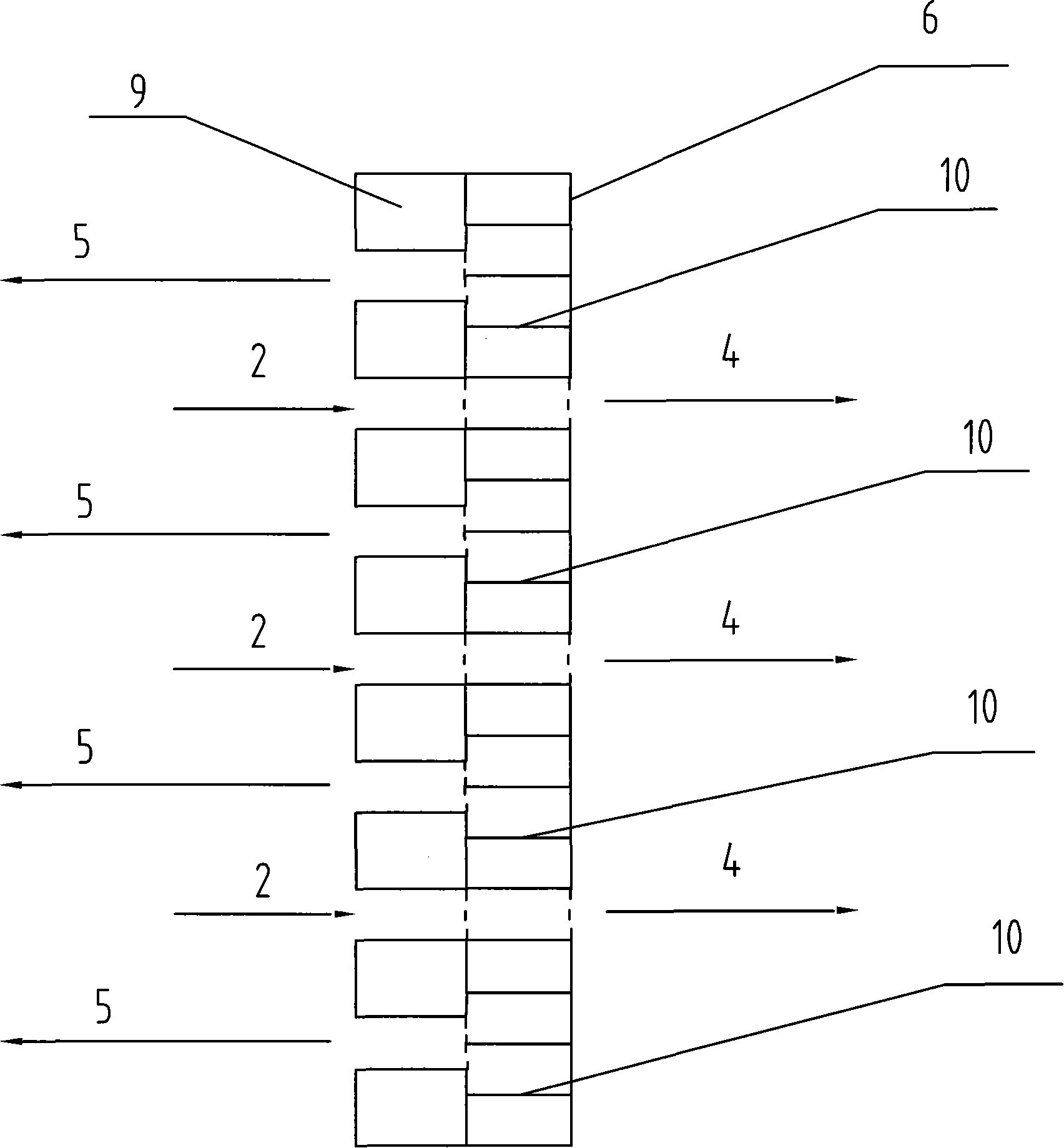
[0032] The rotary pressure swing adsorption gas separator 3 carries six adsorbent components divided by the adsorbent partition 10; the adsorbent components are all filled with 5A molecular sieves. Including the following process steps:

[0033] a. Air pressurized distribution; the mixed gas compressor 1 passes through the gas distributor matched with the rotary pressure swing adsorption gas separator 3, and sends air into the adsorbent assembly equipped with 5A molecular sieve;

[0034] b. High-pressure adsorption: air enters the adsorbent assembly located in the high-pressure adsorption area, nitrogen is absorbed by the adsorbent, oxygen passes through the adsorbent assembly, and is collected after leaving the rotary pressure swing adsorption gas separator 3;

[0035] c. Low-pressure desorption and regeneration: The adsorbent components after high-pressure adsorption are rotated into the low-pressure desorpti...

Embodiment 2

[0037] Embodiment 2 air separation prepares oxygen and nitrogen

[0038] According to the method and steps of Example 1, the rotary pressure swing adsorption gas separator 3 carries 4 adsorbent assemblies divided by the adsorbent partition 10; the adsorbent assemblies are filled with carbon molecular sieves.

Embodiment 3

[0039] Example 3 The decarburization section in the synthetic ammonia production process, the separation of carbon dioxide and synthetic ammonia raw material gas

[0040] According to the method and steps of Example 1, wherein the rotary pressure swing adsorption gas separator 3 carries two adsorbent modules, filled with X-type molecular sieves. Carbon dioxide is firstly adsorbed in the high-pressure adsorption zone, then enters the low-pressure desorption and regeneration zone to be desorbed, and then sent to the carbonization section to synthesize urea, and the rest of the synthetic ammonia raw material gas passes through the adsorbent component and enters the next process.


PUM


Abstract

The invention provides a rotary type pressure-swing-adsorption gas separation method, and belongs to a gaseous mixture separation method, in particular to a method for separating gases with a moving absorbent. The method is characterized in that the method adopts a rotary pressure-swing-adsorption gas separator (3) consisting of a plurality of solid adsorbent components partitioned by absorbent component partitions (10); the gas separation procedure comprises three operation steps of pressurization and delivery of gaseous mixture, absorption of gaseous mixture under high pressure, desorption and regeneration under low pressure. The invention provides the perfect method for rotary pressure-swing-adsorption gas separation which adopts simple devices; needs low investment; saves energy with high productive capacity; and is highly automatic with stable process, and convenient operatation. The absorbent is selected flexibly and has long service life, and little absorbent is used. The method is widely used for gaseous mixture separation during the technological processes of air separation, ammonia synthesis, methanol synthsis, petroleum refining and so on.

Description

technical field [0001] The invention relates to a rotary pressure swing adsorption gas separation method, which belongs to the separation method of mixed gas, and particularly relates to a method for separating gas with a moving adsorbent. Background technique [0002] Since pressure swing adsorption gas separation technology has made significant progress compared with traditional cryogenic liquefaction and fractionation processes, in recent years, it has been used in air separation to produce nitrogen, oxygen and rare argon; carbon dioxide, nitrogen and hydrogen in the ammonia carbonization section Separation; It has been widely used in industrial mixed gas separation processes such as recovering and purifying hydrogen from hydrogen-containing gases. A common pressure swing adsorption gas separation device includes two, four, six or more adsorption towers equipped with fixed bed adsorbents. While one adsorption tower pressurizes and adsorbs gas, the other adsorption tower d...

Claims


Application Information

Patent Timeline
Patent Type & Authority Applications(China)
IPC IPC(8): B01D53/047
Inventor 刘昂峰
Owner 刘昂峰
Why Eureka
Try Eureka