
Plasma ignition high power switch power source

A high-power switch, plasma ignition technology, applied in the direction of output power conversion device, DC power input conversion to DC power output, electrical components, etc., can solve the problem of large volume, slow response speed and low operating frequency of isolation transformers and reactors and other problems, to achieve the effect of fast dynamic response, fast response speed and high working frequency

Inactive Publication Date: 2008-09-24
徐州燃烧控制研究院有限公司
View PDF0 Cites 20 Cited by
  • Summary
  • Abstract
  • Description
  • Claims
  • Application Information

AI Technical Summary

Problems solved by technology

[0003] In recent years, some scientific research institutes and enterprises at home and abroad have devoted themselves to researching the plasma ignition system for the ignition and stable combustion of coal-fired boilers. The plasma ignition combustion device has been used in some power plants, but there are still many problems. The main problems in the above are: the power supply used is a thyristor rectifier power supply, which requires high-power power frequency isolation transformers and reactors, which are huge and heavy; the power electronic devices of the thyristor rectifier power supply work at power frequency, and the response speed Slow; the volume of the isolation transformer and reactor is large, the operating frequency is low, and the loss is large, resulting in low efficiency of the power supply

Method used


Image

  • Plasma ignition high power switch power source
  • Plasma ignition high power switch power source
  • Plasma ignition high power switch power source

Examples


Embodiment 1

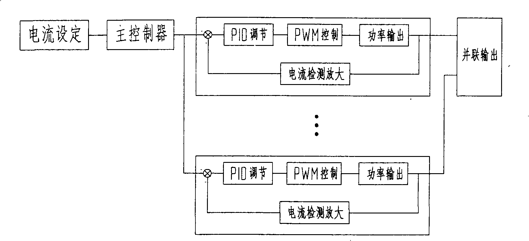
[0027] Embodiment 1: The plasma power supply sets the working current, and the set current signal passes through the main controller to simultaneously control multiple sets of parallel power supply modules, and each set of independent power supply modules outputs current according to the current signal distributed by the main controller, and finally Parallel output normal working current;

[0028] The high-power switching power supply adopts multiple sets of parallel connection; single set of power supply adopts modular design, which is easy to expand; multiple sets of parallel current sharing mode is master-slave mode; the control mode of single set of power supply is average current mode; power redundancy technology to improve reliability.

[0029] The way of multiple groups of parallel connection is not simply to connect the output terminals of multiple power supplies together. When several power supplies with the same structure are operated in parallel, the output terminal...

Embodiment 2

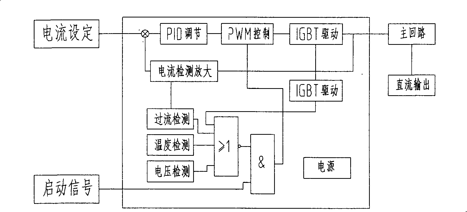
[0036] Example 2: In figure 2 Among them, the working process of the single-group power supply module of the plasma ignition high-power switching power supply of the present invention is as follows: the main controller outputs the flow signal as the setting signal, compares it with the output current signal of the single group, and outputs an error signal to indicate The difference between the actual output current of this group and the current assigned to this group enters the PID regulator for calculation, outputs a control signal, and sends it to the PWM circuit. The PWM circuit generates a corresponding pulse width according to the control signal to adjust the IGBT output, so that the output current of this group equal to the assigned current.

[0037]The single-group power supply module is equipped with a detection circuit and a protection circuit to detect the voltage signal, temperature signal, and current signal, and generate a fault signal together with the IGBT erro...

Embodiment 3

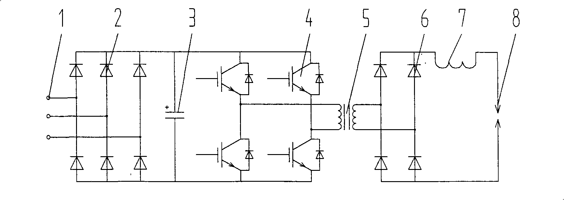
[0039] Example 3: In image 3 Among them, the main circuit principle of the single-group power supply module dedicated to the plasma ignition high-power switching power supply of the present invention is as follows:

[0040] Three-phase AC input 1 is rectified by six rectifier diodes 2 and filtered by capacitor 3 to become DC, and then the full-bridge circuit inverter composed of four IGBT4 is inverted into high-frequency AC square wave pulse voltage, and the full-bridge circuit is inverted The inverter is driven by the control drive protection circuit. The output of the inverter is isolated by the high-frequency transformer 5 and converted into a suitable AC voltage. After being rectified by four high-frequency rectifier diodes 6 and filtered by the reactor 7, it becomes the required DC output voltage to provide Give the plasma arc 8.


PUM


Abstract

A plasma ignition large-power switch power supply belongs to a switch power supply. Working current is set by a plasma switch power supply. A given current signal passes through a main controller and controls multiple groups of power supply modules which are connected in parallel at the same time. Each group of independent power supply module outputs current according to the current signal distributed by the main controller and finally outputs normal working current in parallel. The invention provides single-group power supply modularization, the working form of the multiple groups of power supply modules in parallel connection, the flow equalization form of the multiple groups of power supply modules in parallel connection as a master-slave mode, the control mode of the single-group power supply module as an average current mode and a power redundancy technology. The switch power supply is used in a plasma generator which ignites coal powder directly in a pulverized coal fired boiler to provide large-power direct current power supply and the switch power supply is multiple groups of switch power supplies in parallel connection and outputs high voltage and large current. The flow equalization form of the multiple groups of power supply modules in parallel connection is as the master-slave mode. The control mode of the single-group power supply module is as the average current mode. The power redundancy technology is used so as to improve the reliability. The plasma ignition large-power switch power supply has the characteristic of constant current, smaller volume, weight saving, high working frequency, fast response speed, very little loss and high working efficiency. Modularization design is adopted by the single-group power supply, so as to expand easily.

Description

Technical field [0001] The invention relates to a switching power supply for igniting a pulverized coal boiler, especially a high-power switching power supply for directly igniting pulverized coal when igniting, stabilizing and supporting combustion of a pulverized coal boiler. Background technique [0002] At present, the general ignition method when starting a coal-fired boiler in a power station is: first use the ignition device to ignite the oil burner to increase the temperature and pressure, and when the relevant parameters of the boiler meet the requirements for powder feeding, start the pulverizing system and the pulverized coal burner to realize Operate with load; when the boiler load is reduced to about 50%, it is necessary to inject oil for stable combustion to ensure the normal operation of the boiler. According to statistics, nearly 10 million tons of oil are used in electric power system boilers for ignition, stable combustion, and combustion support each year,...

Claims


Application Information

Patent Timeline
IPC IPC(8): G05F1/66H02M3/335
Inventor 王文举李广伟袁邦银朱德明
Owner 徐州燃烧控制研究院有限公司
Learn More