Micro electro-mechanical system magnetic field sensor and measuring method
A magnetic field sensor, micro-electromechanical system technology, applied in the size/direction of the magnetic field, components of TV systems, piezoelectric/electrostrictive/magnetostrictive devices, etc. The resonator has problems such as high power consumption and low sensitivity, so as to achieve the effect of small temperature influence, high precision, high sensitivity and high precision
- Summary
- Abstract
- Description
- Claims
- Application Information
AI Technical Summary
Problems solved by technology
Method used
Image
Examples
Embodiment 1
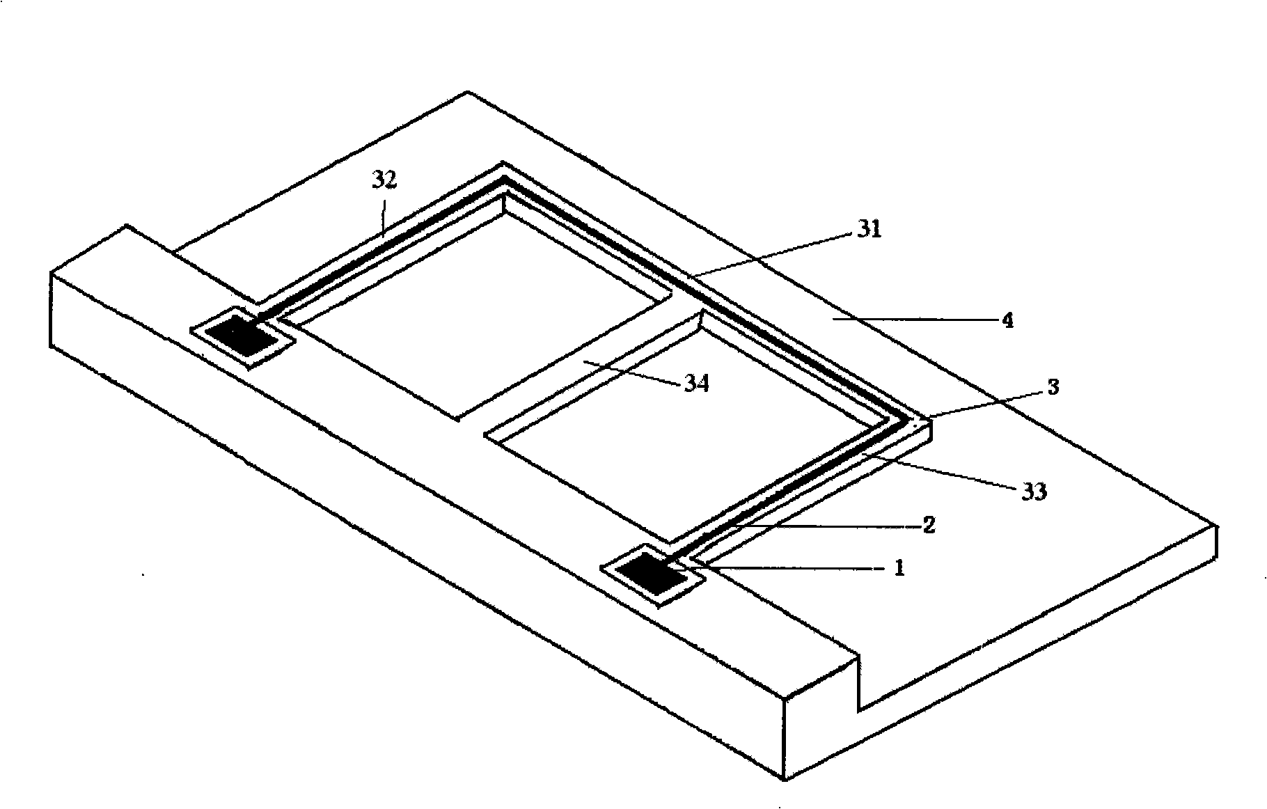
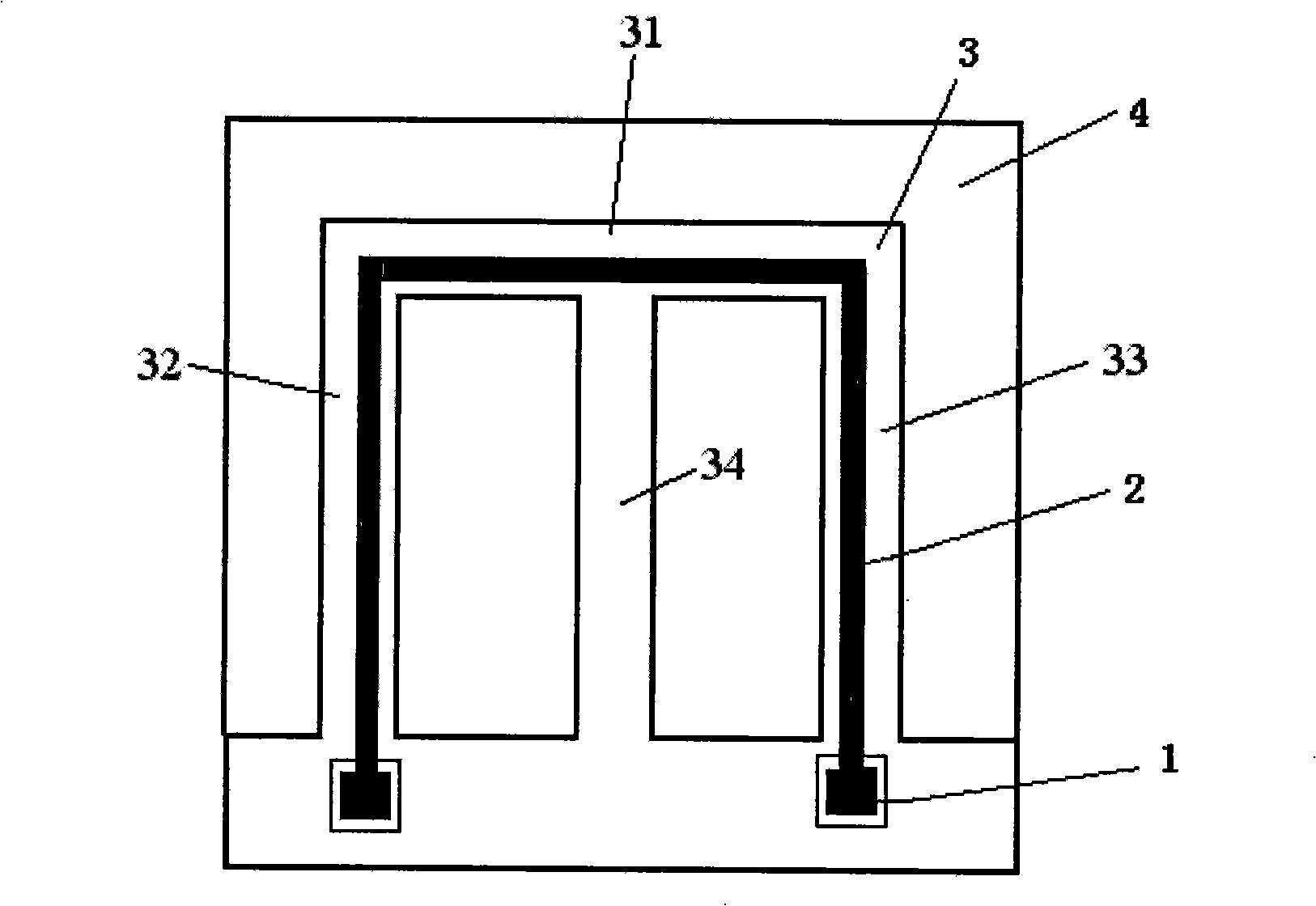
[0032] A micro-electromechanical system magnetic field sensor, including a substrate 4, and also includes an E-shaped cantilever beam 3 and an induced metal wire 2. The E-shaped cantilever beam 3 is arranged on the substrate 4 in parallel, and the induced metal wire 2 is arranged on the E-shaped cantilever beam. on the cantilever beam 3, and can move synchronously with the E-shaped cantilever beam 3. In this embodiment, the induction metal wire 2 can be plated on the upper surface of the E-shaped cantilever beam 3 by evaporation or electroplating, and the metal wire can also be arranged on the above-mentioned position by sputtering. When the electrostatic excitation method is used to vibrate the cantilever beam, an insulating layer needs to be provided between the induction metal wire 2 and the E-shaped cantilever beam 3, and an electrode corresponding to the E-shaped cantilever beam 3 needs to be set on the substrate, so that there is Conducive to adding electrostatic load. ...
Embodiment 2
[0035] A method of measuring using the MEMS magnetic field sensor described in Embodiment 1. First, an external excitation is applied to cause the E-shaped cantilever beam 3 to vibrate, and the induction metal wire 2 that moves synchronously with the E-shaped cantilever beam 3 moves to cut the magnetic force line and sense The strength of the ambient magnetic field can be obtained by generating an induced voltage and then measuring the induced voltage.
[0036] The external excitation can be an external excitation source such as piezoelectric ceramics to make it vibrate; another scheme is: the E-type cantilever 3 is insulated from the substrate 4, and the substrate 4 is correspondingly provided with an E-type cantilever The electrodes parallel to the beam 3, the method of external excitation is: add an AC voltage signal between the E-shaped cantilever beam 3 and the electrodes to make it vibrate, that is, apply electrostatic force to it to vibrate, and apply electrostatic force...
Embodiment 3
[0039] The invention is a MEMS magnetic field sensor for measuring magnetic field, which is composed of a measuring anchor area 1, an induction metal wire 2, an E-shaped cantilever beam 3 and a substrate 4. The sensor takes the substrate 4 as the plane, on the substrate 4 is provided with a sensor structure composed of the induction metal wire 2, the E-shaped cantilever beam 3, and the anchor area 1, which is symmetrical to the center line from left to right, and the induction metal wire 2 can follow the The vibration of the E-shaped cantilever beam 3 moves.
[0040] The induction metal line 2 can be made of Al, Au, etc., and the induction metal line 2 and the measurement anchor area 1 are obtained by etching. The value of the voltage is measured on the induction metal wire 2, and the change of the voltage depends on the magnitude of the magnetic field and the velocity of the cutting magnetic force line of the induction metal wire. The speed can be measured, so the information...
PUM
 Abstract
Description
Claims
Application Information
 - R&D
- Intellectual Property
- Life Sciences
- Materials
- Tech Scout
- Unparalleled Data Quality
- Higher Quality Content
- 60% Fewer Hallucinations
Browse by: Latest US Patents, China's latest patents, Technical Efficacy Thesaurus, Application Domain, Technology Topic, Popular Technical Reports.
© 2025 PatSnap. All rights reserved.Legal|Privacy policy|Modern Slavery Act Transparency Statement|Sitemap|About US| Contact US: help@patsnap.com


