
Super large power electromagnetic suction push-pull driving sound source

An electromagnetic suction, push-pull drive technology, applied in the field of acoustics, can solve the problems of impossible power, limited power, low radiation efficiency, etc., and achieve the effect of reducing nonlinear distortion, high energy conversion efficiency, and high energy utilization rate

Inactive Publication Date: 2009-01-07
INST OF ACOUSTICS CHINESE ACAD OF SCI
View PDF2 Cites 21 Cited by
  • Summary
  • Abstract
  • Description
  • Claims
  • Application Information

AI Technical Summary

Problems solved by technology

The disadvantage is that the power is limited, and it cannot produce super-power (generally above 100 sound watts) acoustic emission; the other is that the efficiency is low
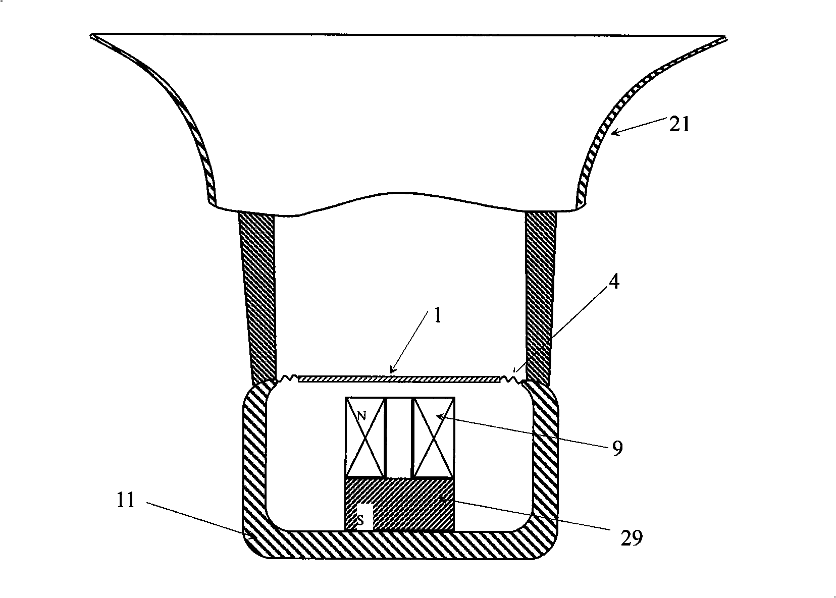
The first problem of this kind of speaker is that its annular permanent magnet and annular magnetic conductive plate do not cover the sound film and voice coil, and there is serious magnetic flux leakage; the second problem is that when the force on the three voice coils is not completely uniform, Only using three-point vibration will cause the diaphragm to vibrate in phase separation, which is easy to damage the diaphragm; the third problem is that the two permanent magnets are opposite to each other with the same polarity, and without forming a closed magnetic circuit, it is easy to demagnetize, so it is impossible to produce a large magnet. power sound output
The first problem with this solution is that the ampere-turn number of the voice coil is low, and it is impossible to generate a large magnetic force, so it is not suitable for generating super-high-power sound; the second problem is that it is a dipole sound source, and the radiation efficiency is low; The three problems are that the generated sound has serious nonlinear distortion; the fourth problem is that there is a coil on the sound film, which is easy to be damaged, and the power cannot be large

Method used


Image

  • Super large power electromagnetic suction push-pull driving sound source
  • Super large power electromagnetic suction push-pull driving sound source
  • Super large power electromagnetic suction push-pull driving sound source

Examples


Embodiment 1

[0074] This embodiment is a push-pull driven electromagnetic suction loudspeaker with a single membrane and double bases, and its structure is as follows: Figure 4 , comprising, upper and lower base yokes 11, upper and lower center yokes 15, upper and lower coils 9, diaphragm 1, intermediate magnetic ring 13, ring 4, throat plug 22, sound outlet 20 and Speaker 21, and a control signal processing circuit.

[0075]In this embodiment, the central yoke 15 is tubular, and the pipeline is an acoustic radiation channel, using manganese-zinc intermediate frequency ferrite soft magnetic material, which has high magnetic permeability (>10000H / m), high resistivity (> 110Ωm), low specific gravity, low coercive force (<4.3A / m), and the working frequency can cover the audio frequency range. The upper and lower base yokes 11 are made of manganese-zinc intermediate frequency ferrite soft magnetic material, and the upper and lower center yokes 15 are mounted on the upper and lower base yokes...

Embodiment 2

[0088] The basic idea of ​​this embodiment is consistent with that of Embodiment 1. In order to further improve the energy utilization rate, the present embodiment uses intermediate frequency silicon steel sheets to make the center yoke 15 and the base yoke 11 . The eddy current of the intermediate frequency silicon steel sheet is small, the magnetic permeability is high, and the insulation between the sheets forms a high resistivity to the eddy current. The use of silicon steel sheet can reduce the eddy current loss of audio current and improve the total energy utilization rate. The intermediate frequency silicon steel sheet can still only have a small eddy current at a frequency of about 15000Hz.

[0089] Such as Figure 12 As shown, this embodiment uses a "mountain"-shaped silicon steel sheet. During use, the silicon steel sheet needs to be pressed tightly and bonded with epoxy resin, and then fixed at a high temperature of 300°C. The magnetically conductive and non-orien...

Embodiment 3

[0097] This embodiment is an ultra-high-power underwater acoustic transducer driven by a double-coil base push-pull electromagnetic. Its basic concept is consistent with that of Embodiment 1. The difference from Embodiment 1 is that a sounding board is used instead of a horn as an acoustic radiator.

[0098] Such as Figure 14 As shown, the present embodiment uses a rigid drive rod 24 (which may also be a pipe or other form of connector) to lead the vibration of the diaphragm 1 to the outer layer, and under the outer sounding plate (ie, the vibration plate 23), rubber ( Promptly after water-seal rubber 28 watertight, need not use just formed the underwater sound transducer like the loudspeaker in the air.The underwater sound transducer of present embodiment, its amplitude is big, and power is big, and operating frequency band, Electric-acoustic conversion efficiency is high.


PUM


Abstract

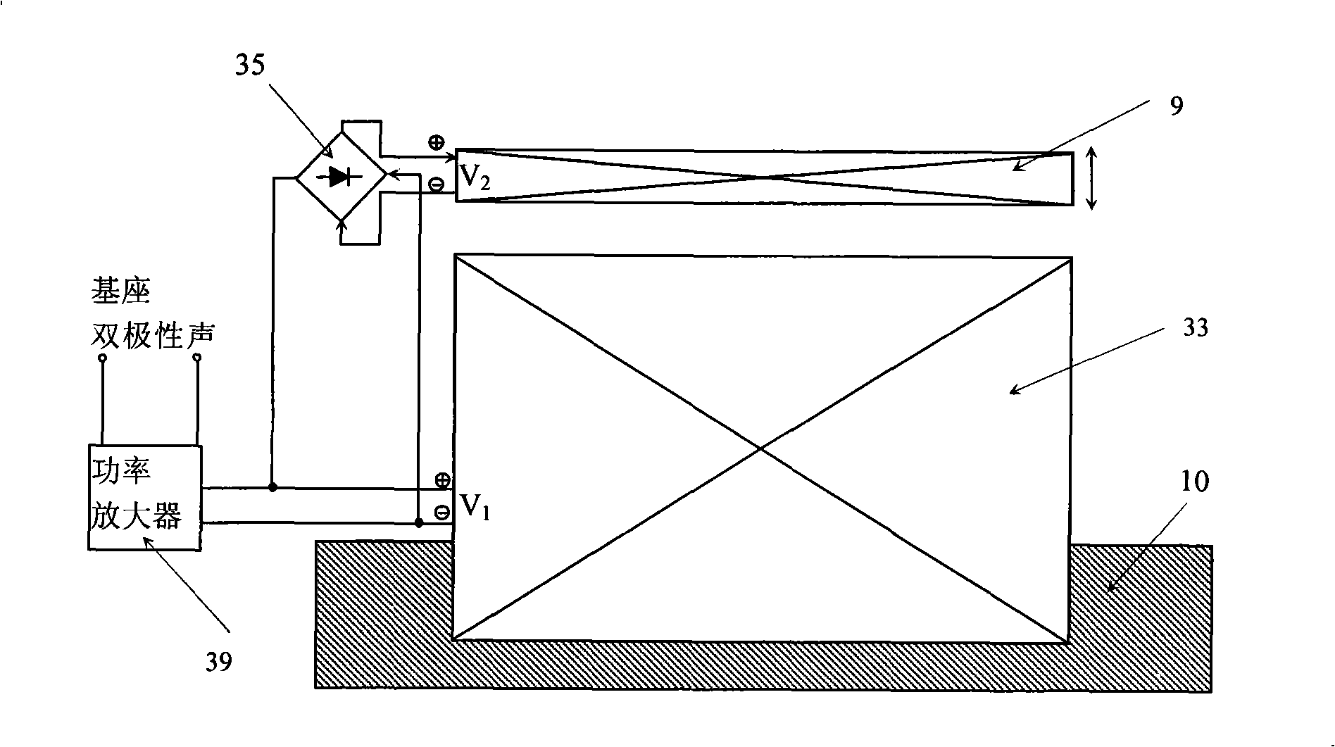
The invention relates to an ultra-large power electromagnetic suction push-pull driving sound source, comprising a base, an upper coil and a lower coil which are arranged inside the base, a vibration part which is arranged at the clearance between the upper coil and the lower coil, and an acoustic radiator which is arranged at the upper side of the base; the upper coil and the lower coil are arranged in the same axle; furthermore, the upper coil and the lower coil have the same winding direction; the sound source also comprises a control signal processing circuit which comprises a half-wave rectifier circuit that respectively provides the positive signal part and the negative signal part of the control signal to the upper coil and the lower coil. The ultra-large power electromagnetic suction push-pull driving sound source has the remarkable advantages that the ultra-large sound power output can be generated, the energy conversion efficiency is high and the nonlinear distortion can be inhibited.

Description

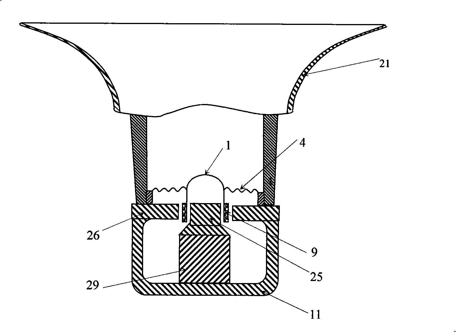
technical field [0001] The invention belongs to the field of acoustics, in particular, the invention relates to a super-high-power electric excitation sound source. Background technique [0002] Traditional electric excitation sound sources include electric, electromagnetic, piezoelectric, magnetostrictive and other forms. Its disadvantage is that the power is limited, and it cannot produce super-power (generally above 100-sound-watt level) acoustic emission; the other is that the efficiency is low. Specifically, as Figure 1a The horn-type electric loudspeaker (or electric underwater acoustic transducer, electric airflow loudspeaker) shown in the figure uses the coil to move linearly under the action of Lorentz force in the magnetic gap to drive the diaphragm 1 to vibrate and produce sound , the driving force is low, and the electro-acoustic conversion efficiency is low; in addition, the amplitude of the coil cannot exceed the length of the magnetic gap; Coil loosening wi...

Claims


Application Information

Patent Timeline
IPC IPC(8): H04R11/00H04R3/00
Inventor 杨亦春
Owner INST OF ACOUSTICS CHINESE ACAD OF SCI
Learn More