Barometric pressure microwave plasma generation device

A technology of microwave plasma and generating device is applied in the field of plasma to achieve the effects of enhancing cooling effect, avoiding erosion and improving energy utilization efficiency

Inactive Publication Date: 2009-01-14
DALIAN MARITIME UNIVERSITY
View PDF0 Cites 27 Cited by
  • Summary
  • Abstract
  • Description
  • Claims
  • Application Information

AI Technical Summary

Problems solved by technology

The rotating airflow generating part 9 can make the...

Method used


Image

  • Barometric pressure microwave plasma generation device

Examples


Embodiment Construction

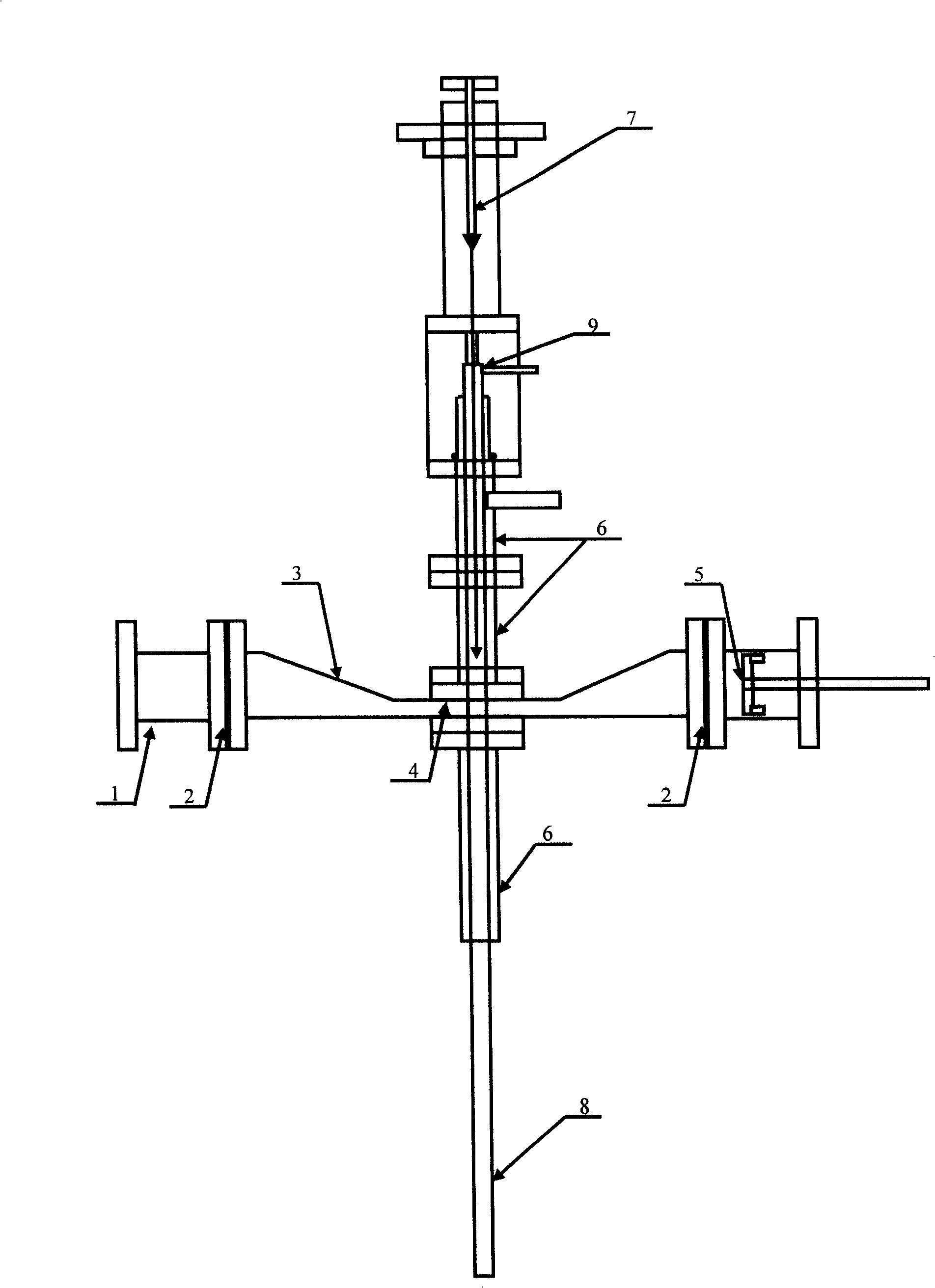
[0011] Such as figure 1 As shown, the generating device consists of a rectangular waveguide 1, a wave-transparent gas sealing film 2, a waveguide conversion mechanism 3, a microwave resonator 4, an adjustable phase matcher 5 at the cut-off end, a reactor 6, an igniter 7, and an outer cooling jacket The pipe 8 and the rotating air flow generating part 9 are composed. The rectangular waveguide 1 is connected to the microwave generator, and the size design generally meets the following requirements: λ


PUM


Abstract

The invention relates to a normal pressure microwave plasma generating apparatus, which consists of a rectangular waveguide, a wave-transparent gas seal membrane, a waveguide changeover mechanism, a microwave resonant cavity, a closure end adjustable phase matching unit, a reactor, a flame lighter, an outer layer cooling collar and a rotating air current generating unit. The microwave transmits in the rectangular waveguide, the reactor is disposed on the geometrical center in the resonant cavity which has the air cooling collar installed outside, the flame light is disposed upon a gas reaction tube and the rotating air current generating unit, the combined type insulated high temperature resistant electrode of the flame lighter is disposed along the inner axis of the quartz tube with the end position adjustable up and down freely. The invention achieves the following advantages: adopting the rectangular waveguide and waveguide conversion can make the microwave energy gathered to process higher power; the power capacity can reach 2KW; the close end can adjust the phase matching unit to generate standing wave in the resonant cavity, ensures the microwave energy coupled to the resonant cavity, reduces microwave reflection loss and improves energy utilization efficiency.

Description

technical field [0001] The invention relates to the technical field of microwave plasma, and in particular provides an atmospheric pressure microwave plasma generating device. Background technique [0002] Compared with dielectric barrier discharge, DC arc, and radio frequency plasma, microwave plasma has the advantages of high energy utilization rate, no electrode pollution, high electron density, and uniform plasma distribution. It is used for chemical synthesis and decomposition, and material surface modification. An ideal process for the degradation and removal of harmful gases. According to the working pressure, microwave plasma can be divided into two types: low pressure less than 0.1MPa and normal pressure 0.1MPa. At present, low-pressure microwave plasma has been widely used in plasma etching and material surface treatment and other fields. Since the gas discharge voltage is proportional to the gas pressure, the pressure of the relatively low-pressure system is rel...

Claims


Application Information

Patent Timeline
IPC IPC(8): H05H1/46H01J37/00
Inventor 孙冰解宏端朱小梅刘永军
Owner DALIAN MARITIME UNIVERSITY
Why Eureka
Try Eureka