Stacking polymer thin-film solar cell with parallel connection structure

A technology of solar cells and polymer films, used in circuits, photovoltaic power generation, electrical components, etc.

Active Publication Date: 2009-04-22
CHANGZHOU INST OF ENERGY STORAGE MATERIALS &DEVICES
View PDF0 Cites 24 Cited by
  • Summary
  • Abstract
  • Description
  • Claims
  • Application Information

AI Technical Summary

Problems solved by technology

There is no report on the realization of parallel structure conjugated polymer thin film solar cells on the same substrate

Method used


Image

  • Stacking polymer thin-film solar cell with parallel connection structure
  • Stacking polymer thin-film solar cell with parallel connection structure
  • Stacking polymer thin-film solar cell with parallel connection structure

Examples


Embodiment 1

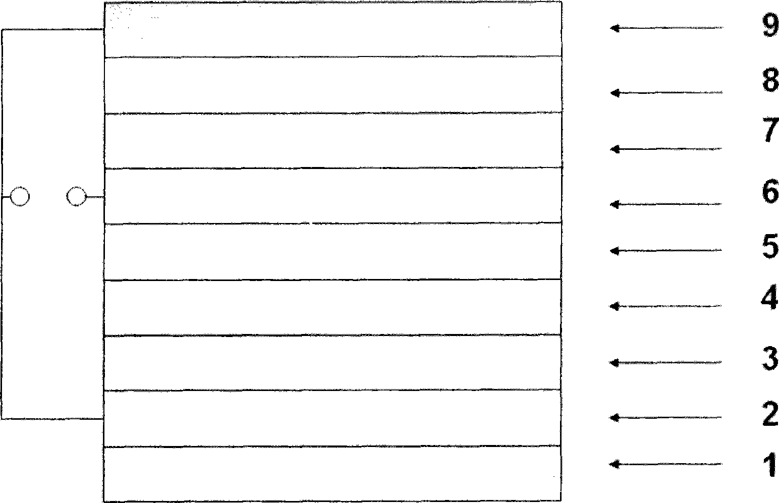
[0035] 1) Clean and dry the etched thin strip-shaped ITO conductive glass with a thickness of 150 nanometers, place it on the bracket of the spin coater, and put TiO2 diluted with absolute ethanol x Evenly coat the entire sheet through a 0.45 μm filter head, and rotate at a speed of 3000 rpm for one minute to obtain 10 nm thick TiO x layer as the electron transport layer 3 of the first sub-cell. Will be coated with TiO x Layered substrates were transferred to a glove box and heated on a hot stage at 150°C for 10 minutes in the glove box to remove TiO x solvent in.

[0036] 2) To be coated with TiO x After the layered ITO conductive glass substrate is cooled to room temperature, it is placed on the bracket of the spin coater, and the mixed solution of PCPDTBT:PCBM that has been stirred is evenly dropped on the TiO x The surface of the layer was spin-coated at a speed of 900 revolutions per minute for one minute to obtain the photosensitive layer 4 of the first sub-cell with...

Embodiment 2

[0044] 1) Clean and dry the etched strip-shaped ITO conductive glass with a thickness of 150 nanometers, place it on the bracket of the spin coater, and evenly coat the ZnO nanoparticles diluted with absolute ethanol through a 0.45 μm filter head. Fill the entire sheet and rotate it at a speed of 1500 rpm for one minute to obtain a 50 nm thick ZnO layer as the first sub-battery electron transport layer 3 . The substrate coated with the ZnO layer was transferred to a glove box, and heated on a hot stage in the glove box at 150° C. for 10 minutes to remove the solvent in the ZnO.

[0045] 2) After the ITO conductive glass substrate coated with ZnO layer is cooled to room temperature, it is placed on the bracket of the spin coater, and the mixed solution of PCPDTBT:PCBM that has been stirred is evenly dropped on the surface of the ZnO layer at 500 revolutions per minute. Rotate at a speed of 1 minute to obtain a photosensitive layer 4 of the first sub-cell of 100 nm.

[0046] Th...

Embodiment 3

[0053] 1) Clean and dry the etched thin strip-shaped ITO conductive glass with a thickness of 150 nanometers, place it on the bracket of the spin coater, and put the SnO diluted with absolute ethanol 2 The sol passed through a 0.45 μm filter head to evenly coat the entire sheet, and rotated at a speed of 2500 rpm for one minute to obtain a 20 nm thick SnO 2 layer as the electron transport layer 3 of the first sub-cell. will be coated with SnO 2 Layered substrates were transferred to a glove box and heated on a hot stage at 150°C for 10 minutes in the glove box to remove SnO 2 solvent in.

[0054] 2) to be coated with SnO 2 After the layered ITO conductive glass substrate is cooled to room temperature, it is placed on the bracket of the spin coater, and the mixed solution of PCPDTBT:PCBM that has been stirred is evenly dropped on the SnO 2 The surface of the layer was rotated at a speed of 1000 rpm for one minute to obtain the photosensitive layer 4 of the first sub-cell wi...


PUM

PropertyMeasurementUnit
thicknessaaaaaaaaaa
thicknessaaaaaaaaaa
thicknessaaaaaaaaaa

Abstract

The invention provides a tandem polymer solar cell with a parallel structure. In the solar cell, metals with a high work function such as gold and sliver are taken as a semitransparent anode to extract holes. A p-type metal oxide molybdenum trioxide or tungsten oxide is taken as a hole transport layer at two sides of the anode for connecting an upper sub-cell photosensitive layer and a lower sub-cell photosensitive layer so as to construct a built-in electric field and improve the collection efficiency of a current carrier. The photosensitive layers of an upper sub-cell and a lower sub-cell in the tandem cell are respectively a mixture consisting of a conjugated polymer and a fullerene derivative with different absorption ranges. The two sub-cells are connected in parallel, and short circuit current density of the tandem solar cell is the sum of the short circuit current density of the upper sub-cell and the short circuit current density of the lower sub-cell. By conjugated polymers with the different absorption ranges, the tandem polymer thin film solar cell effectively improves the active sunlight absorption and realizes that the short circuit current is effectively increased to 15 milliampere/square centimeter, thus increasing the maximum energy conversion efficiency of the polymer thin film solar cell to 3.36%.

Description

technical field [0001] The invention relates to a laminated polymer thin film solar cell with a parallel structure. Background technique [0002] Conjugated polymer thin film solar cells can be prepared by continuous printing, which can effectively reduce production costs; especially due to the lightweight and flexible characteristics of polymer thin film solar cells, the original fixed plane installation mode can be applied to different curved surfaces and flexible, Portable multi-application channel expansion, flexible installation and low cost. This new type of solar cell has a wide range of applications, for example: it can be installed on roofs and walls, or it can be made into blinds and awnings that can generate electricity; it can also be used as a portable charging device to power laptops, mobile phones, digital music players, etc. At present, the energy conversion efficiency of conjugated polymer thin film solar cells is relatively low. One of the main problems is...

Claims


Application Information

Patent Timeline
Patent Type & Authority Applications(China)
IPC IPC(8): H01L51/42H01L51/46
CPCY02E10/50Y02E10/549
Inventor 谢志元郭晓阳刘凤敏耿延候岳威屈瑶王利祥
Owner CHANGZHOU INST OF ENERGY STORAGE MATERIALS &DEVICES
Why Eureka
Try Eureka