Method for preparing solar energy level silicon crystals containing doped element

A doping element, solar-grade technology, applied in the silicon crystal field of high-conversion-efficiency solar cells, can solve problems such as uneven resistivity distribution and small segregation coefficient of gallium-doped silicon ingots, so as to improve photoelectric conversion efficiency and minority-carrier lifetime The effect of improving and improving the life expectancy of the minority

Inactive Publication Date: 2009-10-21
GREENERGY CRYSTAL TECH
View PDF2 Cites 23 Cited by
  • Summary
  • Abstract
  • Description
  • Claims
  • Application Information

AI Technical Summary

Problems solved by technology

[0007] In the experiment of using gallium instead of boron as the doping element, the problem of uneven resistivity distribution of gallium-doped silicon ingots was encountered due to the small segregation coefficient of gallium (k=0.008).

Method used


Image

  • Method for preparing solar energy level silicon crystals containing doped element
  • Method for preparing solar energy level silicon crystals containing doped element
  • Method for preparing solar energy level silicon crystals containing doped element

Examples


Embodiment 1

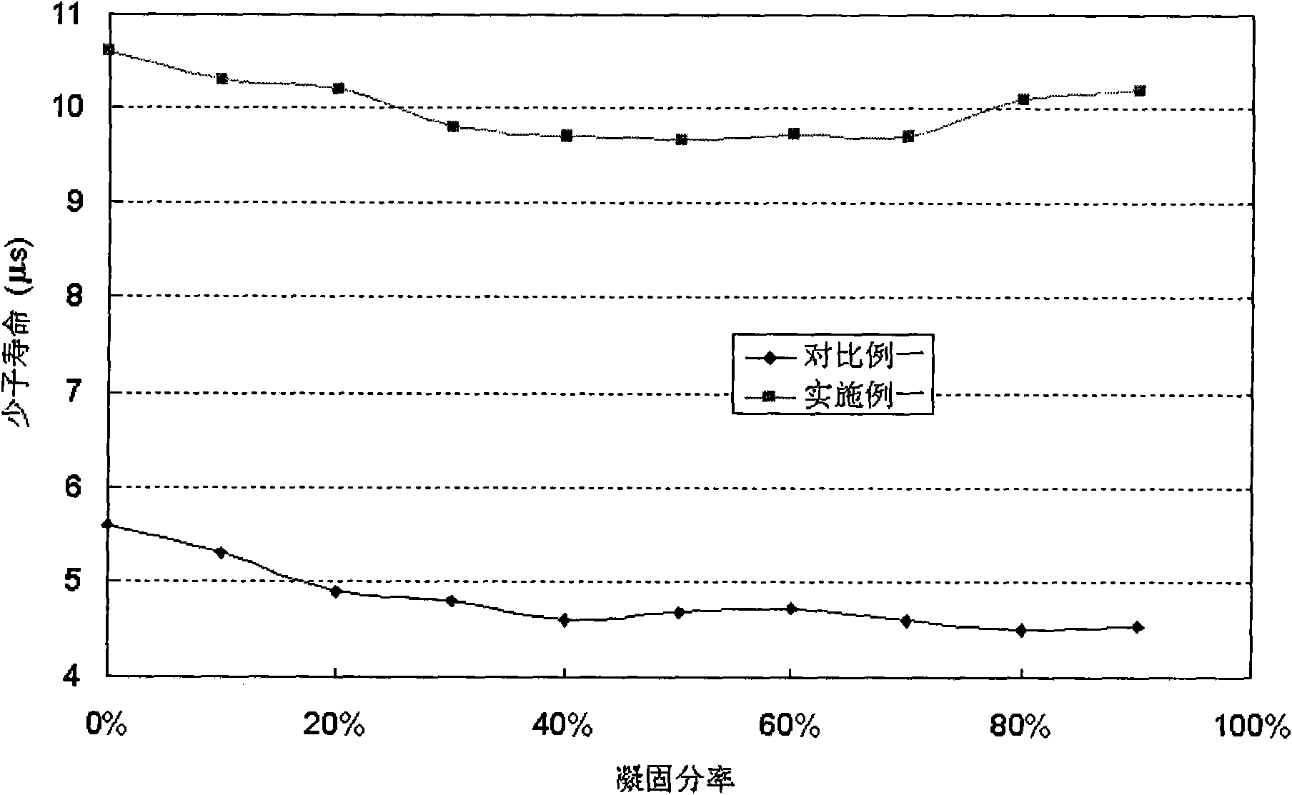
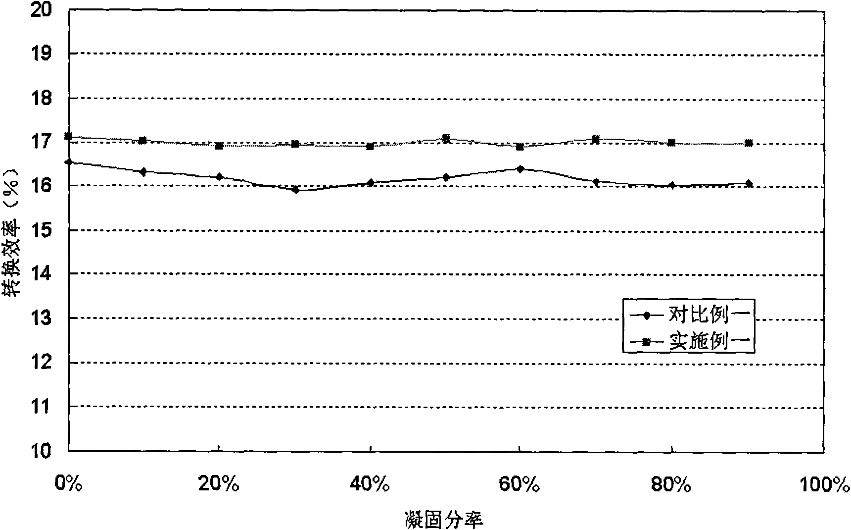
[0050] The Czochralski method was used to prepare silicon crystals for the manufacture of high conversion efficiency solar cells. 50Kg of raw material is put into the furnace, and its mass percentage composition is composed of 50% primary polysilicon material and 50% boron-containing crucible bottom material. Among them, the primary polysilicon material contains 0.5 mg of boron and 0.1 mg of phosphorus. Boron in the bottom material of the crucible is 5.5 mg, and phosphorus in the bottom material of the crucible is 0.9 mg. 100% Ar gas was introduced to protect the material. After the chemical material is completed, the gas that is passed into is changed to 40% H by volume percentage. 2 Gas, a protective gas composed of 60% Ar gas. Properly adjust the flow rate of the protective gas and the pumping rate of the vacuum pump to control the pressure in the furnace at about 1000Pa, and the flow rate of the protective gas through the surface of the silicon melt is 40slpm / m 2 . Wh...

Embodiment 2

[0056] The directional solidification method (using DSS method polysilicon ingot furnace) is used to prepare silicon crystals for manufacturing high conversion efficiency solar cells. In the polysilicon ingot furnace, the silicon melt (doped with phosphorus with a mass concentration of 0.1ppmw) is stored in a quartz crucible, and the protective gas composed of 50% argon and 50% hydrogen by volume is passed through the conductor. The gas pipe is introduced from the top of the polysilicon ingot furnace. The flow rate of shielding gas through the surface of silicon melt is 60slpm / m 2 . By changing the heating power of the heater to adjust the temperature field distribution in the furnace, the silicon crystal grows upward from the bottom of the quartz crucible to prepare the silicon crystal. When the silicon is completely crystallized, continue to pass the protective gas until the temperature of the silicon crystal is lower than 500°C.

Embodiment 3

[0058] Using the process of Example 1 to prepare boron-doped silicon crystals, the difference is that the protective gas is 100% by volume of SiH 4 gas composition.


PUM


Abstract

The invention discloses a method for preparing solar energy level silicon crystals containing doped element, which is to place molten silicon containing the doped element into a crucible reactor and adopt a directional solidification method or a pulling method to prepare the silicon crystals. In the preparation process of the silicon crystals, protective gas is introduced into a crystal growing furnace and flows through the surface of the molten silicon, and is as follows: a) gas containing hydrogen atoms; or b) a mixture of the gas containing the hydrogen atoms and inert gas. The method obviously improves the minority-carrier lifetime of the silicon crystals by the functions of H on passivation, gettering and the like of impurities and defects in the silicon crystals, and improves the photoelectric conversion efficiency of subsequently manufactured cell slices. The method also adjusts the resistivity of silicon crystals doped with gallium and makes the resistivity of the silicon crystals more uniform in the crystal growing direction. Moreover, the method is simple in operation and easy in industrialized production, and can obviously improve the product quality.

Description

technical field [0001] The invention relates to a method for preparing silicon crystals, in particular to a method for preparing silicon crystals for solar cells with high conversion efficiency by using a Czochralski method or a directional solidification method. Background technique [0002] The raw silicon crystals used in the preparation of crystalline silicon solar cells are divided into silicon single crystals or silicon polycrystals. The commonly used production methods for silicon crystals are directional solidification methods. Typical methods of this type of methods include Bridgman method, Heat Exchange Method (HEM) method and Directional Solidification System (DSS) method. Its characteristic is that by changing the temperature field distribution in the crystal growth furnace (such as passing the cold source from the bottom of the ingot furnace or changing the position of the heater or heat preservation material in the furnace) to form an appropriate temperature gr...

Claims


Application Information

Patent Timeline
Patent Type & Authority Applications(China)
IPC IPC(8): C30B29/06C30B27/00
Inventor 李乔马远
Owner GREENERGY CRYSTAL TECH
Why Eureka
Try Eureka