
Method and device for removing phosphorus and boron in polysilicon by continuous smelting

A polysilicon and electron gun technology, applied in chemical instruments and methods, self-area melting method, silicon and other directions, can solve the problems of low primary conversion rate, long process time, and many process links, and achieve good purification effect, stable technology, The effect of improving purity

Inactive Publication Date: 2010-05-19
DALIAN UNIV OF TECH
View PDF1 Cites 9 Cited by
  • Summary
  • Abstract
  • Description
  • Claims
  • Application Information

AI Technical Summary

Problems solved by technology

The disadvantage of the Siemens method is that it adopts backward thermal chemical vapor deposition in the core link of the process. There are too many links in the process and the conversion rate is low at one time, which leads to a long process time and increases the cost of materials and energy consumption.
The simple directional solidification method cannot remove the impurity phosphorus with a large segregation coefficient. Among the many impurities in polysilicon, boron is a harmful impurity, which directly affects the resistivity and minority carrier lifetime of silicon materials, and then affects the performance of solar cells. Photoelectric conversion efficiency
The phosphorus content of polycrystalline silicon that can be used to prepare solar cells is required to be reduced to less than 0.00003%. It is known that the invention patent of Japanese Patent No. 11-20195 uses electron beams to achieve the purpose of removing phosphorus in polycrystalline silicon, but this patent cannot use electron beams to remove boron. In the known invention patents and scientific papers, there is no application of electron beams to simultaneously remove phosphorus and boron in one device

Method used


Image

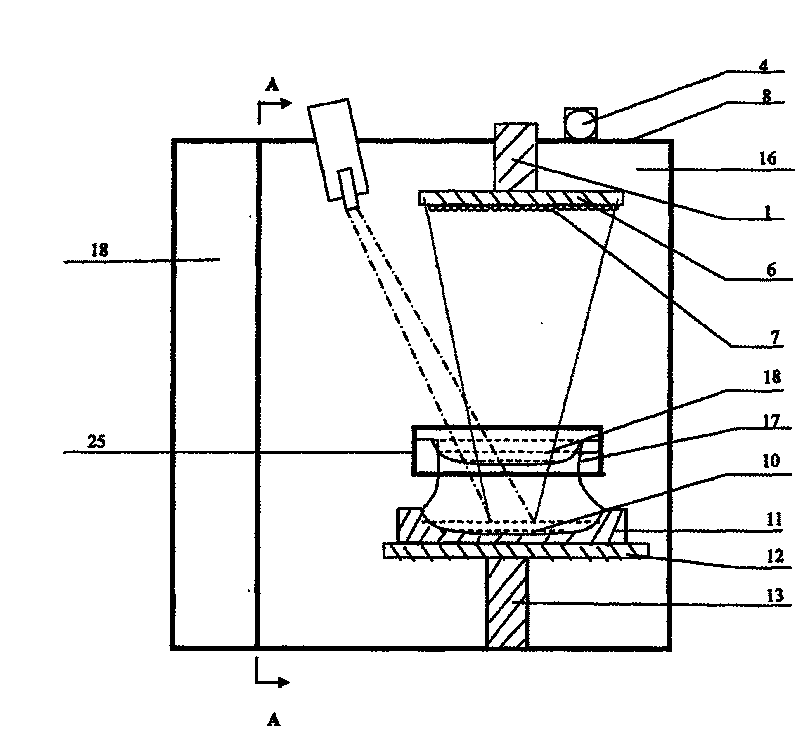
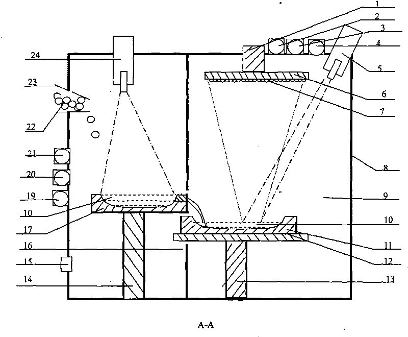
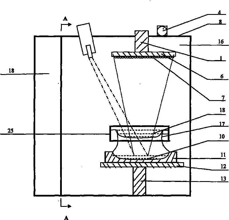
  • Method and device for removing phosphorus and boron in polysilicon by continuous smelting
  • Method and device for removing phosphorus and boron in polysilicon by continuous smelting
  • Method and device for removing phosphorus and boron in polysilicon by continuous smelting

Examples


Embodiment Construction

[0021] The specific implementation of this solution will be described in detail below with reference to the technical solution and the accompanying drawings.

[0022] According to the Langmuir equation where ω B for evaporation γ B(l)inSi o rate, P B is the saturated vapor pressure of boron, M B is the atomic weight of boron atoms, T is the temperature of the molten pool, and is the activity coefficient of boron in silicon. Since the saturated vapor pressure of boron is very low, when silicon is smelted at high temperature, the boron contained in the silicon vapor is only less than 1% of the silicon matrix, and the evaporated silicon vapor is collected to achieve the purpose of removing boron.

[0023] Put the polysilicon material 22 containing 0.0005% boron and 0.0007% phosphorus into the water-cooled copper crucible 17, and the polysilicon material 22 is loaded with a third position of the water-cooled copper crucible 17, and the vacuum cover 25 is closed; the vacuumin...


PUM


Abstract

The invention belongs to the technical field of polysilicon purification by a physical metallurgy technology, in particular to a method for removing phosphorus and boron of impurities in polysilicon by an electron beam smelting technology. In the method, two electron guns are used for emitting electron beams to respectively smelt the polysilicon; meanwhile, the phosphorus and the boron in the polysilicon are removed by a dual technology; the phosphorus in the polysilicon is removed at first, the polysilicon with low phosphorus is further smelted and evaporated to remove the boron; and the polysilicon with low phosphorus and boron, which is evaporated, on a depositing plate is collected. The adopted device comprises a shell and a vacuum chamber, wherein the shell comprises a vacuum cover and a vacuum barrel; an inner cavity of the vacuum barrel is the vacuum chamber; and the vacuum chamber comprises a left cavity and a right cavity which are partitioned by an isolating plate. The invention effectively improves the purity of the polysilicon, reaches the use requirement of solar energy-grade silicon and has good purifying effect, stable technology and high efficiency.

Description

technical field [0001] The invention belongs to the technical field of purifying polycrystalline silicon by physical metallurgy technology, and particularly relates to a method for removing impurities phosphorus and boron in polycrystalline silicon by using electron beam smelting technology. Background technique [0002] High-purity polysilicon is the main raw material for preparing solar cells. The Siemens method is mainly used for the preparation of high-purity polysilicon abroad, specifically the silane decomposition method and the gas-phase hydrogen reduction method of chlorosilane. The Siemens method is currently the mainstream technology for the preparation of polysilicon. Its useful deposition ratio is 1×10 3 , 100 times that of silane. The deposition speed of the Siemens method can reach 8 to 10 μm / min. The conversion efficiency of one pass is 5%~20%, and the deposition temperature is 1100℃, second only to SiCl 4 (1200℃), the power consumption is about 120kWh / kg,...

Claims


Application Information

Patent Timeline
IPC IPC(8): C01B33/037
CPCC01B33/02H01L31/182C30B13/00Y02E10/546C01B33/037Y02P70/50
Inventor 谭毅董伟李国斌姜大川
Owner DALIAN UNIV OF TECH
Learn More