Method and device for removing sulfur dioxide and nitric oxide by combining dual-shaft clash smoke gas

A technology for sulfur dioxide and nitrogen oxides, applied in chemical instruments and methods, separation methods, air quality improvement, etc., to achieve high comprehensive efficiency, improved uniformity, and wide application range

Inactive Publication Date: 2010-06-23
SOUTHEAST UNIV
View PDF3 Cites 13 Cited by
  • Summary
  • Abstract
  • Description
  • Claims
  • Application Information

AI Technical Summary

Problems solved by technology

At present, there is only one utility model patent (ZL 200820042363.1) in China that uses impinging flow technology in the process of alkali desulfurization. The hi

Method used


Image

  • Method and device for removing sulfur dioxide and nitric oxide by combining dual-shaft clash smoke gas
  • Method and device for removing sulfur dioxide and nitric oxide by combining dual-shaft clash smoke gas
  • Method and device for removing sulfur dioxide and nitric oxide by combining dual-shaft clash smoke gas

Examples


Example Embodiment

[0034] Example 1

[0035] A method for combined removal of sulphur dioxide and nitrogen oxides by biaxial collision flow flue gas,

[0036] The polluted flue gas containing sulfur dioxide and nitrogen oxides is dedusted and enters the heat exchanger to cool down to 100℃~110℃,

[0037] Then the flue gas after dust removal and cooling enters the biaxial impinging flow premixing tube. In the biaxial impinging flow premixing tube, the flue gas is firstly mixed with the atomized urea / ammonia mixed with catalytic additives The mixed solution is premixed with gas and liquid, and the temperature of the absorption liquid is controlled at 30℃~80℃, among which the liquid gas ratio is 1.5~6L / m 3 , The mass concentration of the aqueous ammonia solution is 2%-10%, the mass concentration of the urea solution is 2%-6%, the PH value of the absorption solution is maintained at 4.8-9, the catalytic additives are potassium bromide, ammonium bromide, Potassium chloride, ammonium chloride, ammonium persu...

Example Embodiment

[0040] Example 2

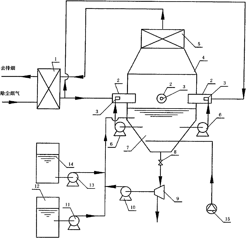
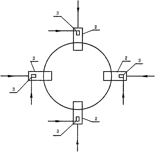
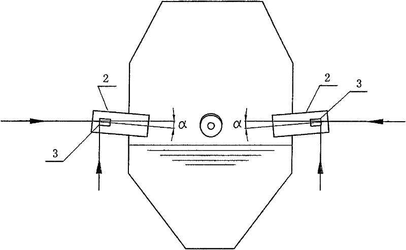
[0041] A device for implementing the method for the combined removal of sulfur dioxide and nitrogen oxides from the dual-axis impinging flow flue gas described in Example 1, consisting of a heat exchanger 1, a dual-axis impinging flow premixing tube 2, and an impinging flow reactor Main body 4, high-efficiency demister 5, absorption liquid circulation pump 6, sump 7, valve 8, centrifuge 9, separation liquid pump 10, ammonia pump 11, ammonia solution tank 12, urea solution pump 13, urea solution preparation The liquid tank 14 and the air compressor 15 are composed. The polluted flue gas outlet of the heat exchanger 1 is respectively connected with the flue gas inlet of the biaxial impinging flow premixing tube 2, and the absorption solution is stored in the liquid collecting tank 7 and collected The liquid tank 7 is connected to the lower end of the impinging flow reactor main body 4. The biaxial impinging flow premixing tube 2 is arranged on the impinging flow ...


PUM


Abstract

The invention relates to a method for removing sulfur dioxide and nitric oxide by combining dual-shaft clash smoke gas, comprising the following steps of: dedusting and cooling polluted smoke gas to enter a dual-shaft clash stream premixing pipe, performing gas-liquid premixing with urea/ammonia water mixing solution in the dual-shaft clash stream premixing pipe, controlling the temperature of absorption liquid at 30 to 80 DEG C, accelerating the absorption liquid by smoke gas in the dual-shaft premixing pipe and entering a clash stream reactor body. A device is composed of a heat exchanger, a dual-shaft clash premixing pipe, a clash stream reactor body, an efficient demister, an absorption liquid circulation pump, a liquid collecting tank, a valve, a centrifuge, a separation liquid pump, an ammonia water pump, an ammonia water liquid distributing tank, a urea solution pump, a urea solution distributing tank and an air compressor. The dual-shaft clash stream premixing pipe comprises two pairs of clash stream premixing pipes each of which comprises two premixing pipes arranged in the same direction; the premixing pipe is provided with an absorption liquid atomizing nozzle; and the two pairs of clash stream premixing pipes form orthogonality relation in the same horizontal plane.

Description

technical field [0001] The invention belongs to the technical field of atmospheric environment protection. It relates to a flue gas combined desulfurization and denitrification method and device, in particular to a method and device for flue gas combined desulfurization and denitrification using urea / ammonia water / additive solution biaxial counterflow flue gas. Background technique [0002] Sulfur dioxide and nitrogen oxides are the most influential gaseous pollutants in the air pollutants, which are extremely harmful to the human body, the environment and the ecological system. With the increasingly stringent environmental protection requirements, NO x and SO 2 The issue of emissions is getting more and more attention. Sulfur dioxide and nitrogen oxides are mainly derived from the combustion process of coal, petroleum and other petrochemical fuels, as well as the flue gas emissions from the roasting and smelting of ores. It is difficult to manage due to its characteristi...

Claims


Application Information

Patent Timeline
IPC IPC(8): B01D53/78B01D53/60
CPCY02A50/20
Inventor 熊源泉谢红银
Owner SOUTHEAST UNIV
Why Eureka
Try Eureka