Thermal deposition surface treatment method, system and product

一种热沉积、热处理装置的技术,应用在热处理炉、热处理设备、炉等方向,能够解决窄误差容限、控制温度即热堆积和工件内热均匀性困难等问题,达到过程波动可靠的效果

Inactive Publication Date: 2010-06-23
AIR PROD & CHEM INC
View PDF6 Cites 17 Cited by
  • Summary
  • Abstract
  • Description
  • Claims
  • Application Information

AI Technical Summary

Problems solved by technology

Although cryogenic cooling methods offer a significant increase in the ability to quickly remove heat, they are rarely used in the thermal deposition coating industry because it is even more difficult to control the temperature during coating, i.e. heat build-up and heat uniformity within the workpiece or narrower error margin

Method used


Image

  • Thermal deposition surface treatment method, system and product
  • Thermal deposition surface treatment method, system and product
  • Thermal deposition surface treatment method, system and product

Examples


Embodiment 1

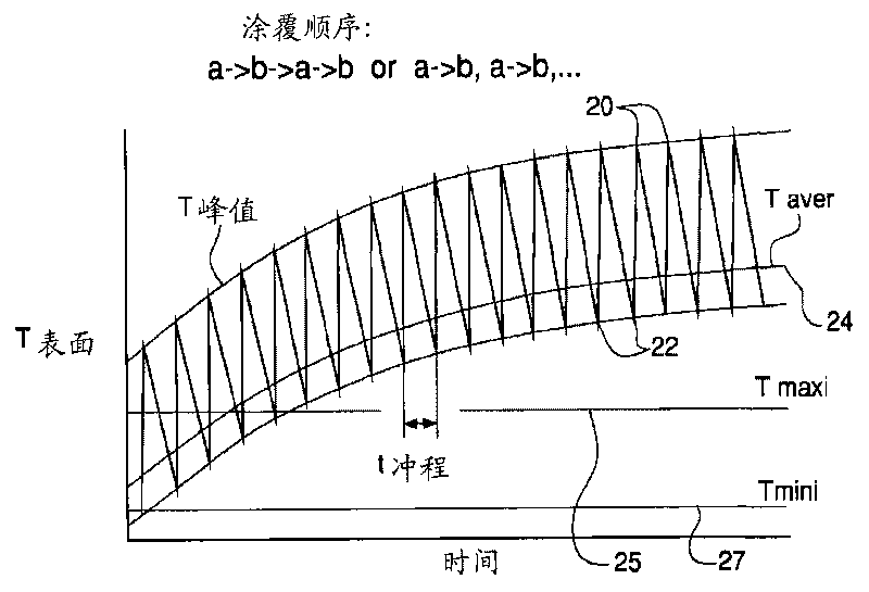
[0065] The purpose of this example is to more fully explain the Figure 6 Control parameters enumerated in the description of the process steps shown. Figure 4 , 5 and 6 are used to make the description easy.

[0066] Figure 4 A thermal deposition method is illustrated using a workpiece 40 comprising a workpiece base surface 41 having a cylindrical shape and being rotated during the thermal deposition coating method. A workpiece (RW) comprising a workpiece substrate surface 41 is mounted in a remotely actuated rotating carriage (RWA) 42 and exposed to thermal coating deposition material 46 from a thermal deposition head (TCD) 44, thermally deposited The head (TCD) 44 is in turn traversed across the workpiece surface by a separate brake mount (TCDA) arrangement. Simultaneously moving laterally with the thermal deposition head 44 is an elongated cryogenic coolant distributor (SCMD) 48 which provides a cooling effect on only the coated portion of the substrate 41 or on unco...

Embodiment 2

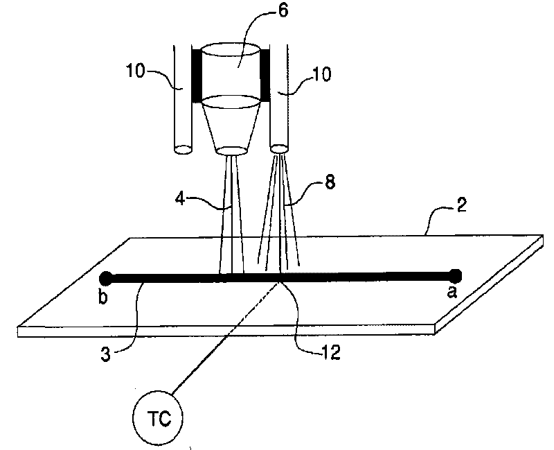
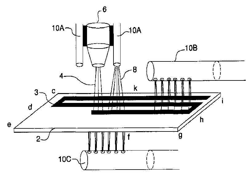
[0073] image 3 A diagram of a thermal deposition process for workpieces optionally using laterally moving and stationary cryogenic coolant delivery systems. and figure 1 Those common equipment components shown are numbered similarly. In illustrating a method of establishing cooling in a thermal deposition coating operation using a cryogenic gaseous coolant medium, coolant 8 is provided by one or more coolant devices 10A, 10A', 10B, and 10C. These coolant devices such as 10A, 10A' can move with the thermal deposition head 4, Figure 4 The dispenser 48 shown in the figure moves as it moves, or remains stationary. Due to the resulting stress distribution, it is more necessary to cool the top side of the workpiece, which is the surface of the workpiece to be coated, where heat is deposited together with the coating material, than the rear side of the workpiece. Of course, cooling the top side of the workpiece surface is more difficult, whether or not the cooled portion o...

Embodiment 3

[0076]Industrial trials of the present system and method were conducted during HVOF spray coating operations involving WC-Co coating materials. The HVOF gun sprays 45 grams of WC-Co powder per minute on a long and narrow rotating aircraft landing gear component made of high-strength steel. The surface speed of the rotating part was 150 ft / min, the gun traverse speed was 1 / 8 inch per revolution, and the distance between the gun nozzle and the part surface was about 9 inches. The HVOF flame is hydrogen-oxygen with a hydrogen flow rate of 1525 scf / hr at 150 psig supply pressure and an oxygen flow rate of 475 scf / hr at 165 psig supply pressure. Four cryogenic fluid nozzles were positioned approximately evenly along the axis of the rotating member at a distance of about 4 inches from the surface of the rotating member. The nozzles discharge a 2-phase mixture of cryogenic nitrogen vapor and a spray of mist-sized liquid droplets to the surface for cooling. The cryogenic fluid suppl...


PUM


Abstract

A process for treating a workpiece, said process comprising the steps of: (c) altering the temperature of a workpiece surface wherein at least one condition selected from the group of: thermal treatment rate, relative motion between the surface and said thermal treatment rate, coolant flow rate onto said surface, heating flow rate onto said surface and the relative speed between the heating means or the cooling means and the surface is controllable; (d) simultaneously measuring temperatures at a plurality of locations over the surface of the workpiece; (c) determining an average temperature of the temperatures measured in step (b); (d) comparing the average temperature to a preselected minimum temperature and a preselected maximum temperature for the workpiece; and (e) automatically adjusting at least one of the controllable conditions if said average temperature is not between the preselected minimum temperature and the preselected maximum temperature for the workpiece. A system for performing a thermal treatment process and the resulting product are also provided. Standard deviations of all temperature readings and controlling the relative motion speed between the thermal coating deposition head and the workpiece provide another improvement for obtaining temperature uniformity over the workpiece surface.

Description

[0001] This application claims priority to provisional application 60 / 851197, filed October 12, 2006, entitled "Thermal Deposition Surface Treatment Method, System and Product," which is incorporated herein by reference in its entirety. Background of the invention [0002] Methods of applying various coatings such as metals, alloys, ceramics and composite materials to various substrates to form component products using thermal deposition coating methods are known. Use this method to improve the properties of the substrate such as hardness, corrosion resistance, heat resistance, surface porosity, etc. Exemplary thermal deposition coating operations include: high velocity oxy-fuel spray (HVOF) and high velocity air-fuel spray (HVAF), DC and RF plasma spray in air atmospheres, vacuum chambers and / or inert gas chambers, arc ( twin wire and single wire) spraying, laser powder coating or cladding, transferred arc coating operations such as plasma transferred arc powder coating and w...

Claims


Application Information

Patent Timeline
Patent Type & Authority Applications(China)
IPC IPC(8): C23C4/02C23C8/02C23C10/02C23C24/02
CPCC23C24/02C23C8/02Y02T50/67C23C4/02C23C10/02Y02P10/25C21D9/00C23C8/00C23C14/58C23C16/56Y02T50/60
Inventor Z·朱雷基C·A·沃德
Owner AIR PROD & CHEM INC
Why Eureka
Try Eureka