Magnetic-particle photocatalyst with core-shell structure, preparation and application thereof

A photocatalyst and magnetic particle technology, applied in physical/chemical process catalysts, metal/metal oxide/metal hydroxide catalysts, inorganic material magnetism, etc. Inefficiency, etc.

Active Publication Date: 2013-05-15
NANJING UNIV
View PDF0 Cites 0 Cited by
  • Summary
  • Abstract
  • Description
  • Claims
  • Application Information

AI Technical Summary

Problems solved by technology

However, photocatalytic technology has not yet been industrialized in water treatment and wastewater treatment, and there are two main problems: (1) The photocatalytic system of the suspension system has high photocatalytic efficiency, and there is a problem of after-treatment of the catalyst. If the photocatalyst is fixed on glass and other materials It can solve the problem of separation and recovery of photocatalyst, but its photocatalytic efficiency is significantly lower than that of the suspension system; (2) titanium dioxide can only absorb ultraviolet light, has no response in the visible light range, and has a low utilization rate of sunlight (4%), while The ultraviolet part of the solar spectrum accounts for less than 5%, while the visible light with a wavelength of 400-750nm accounts for nearly 43%. If the ultraviolet and visible light bands in sunlight can be fully utilized at the same time, the photon quantum efficiency will increase greatly improved
The specific gravity of the photocatalyst is greater than that of water, and it is in a sinking state in the suspension system. Although the stirring effect can solve the uneven distribution of the catalyst to a certain extent, it can only treat the symptoms but not the root cause.

Method used


Image

  • Magnetic-particle photocatalyst with core-shell structure, preparation and application thereof
  • Magnetic-particle photocatalyst with core-shell structure, preparation and application thereof
  • Magnetic-particle photocatalyst with core-shell structure, preparation and application thereof

Examples


Embodiment Construction

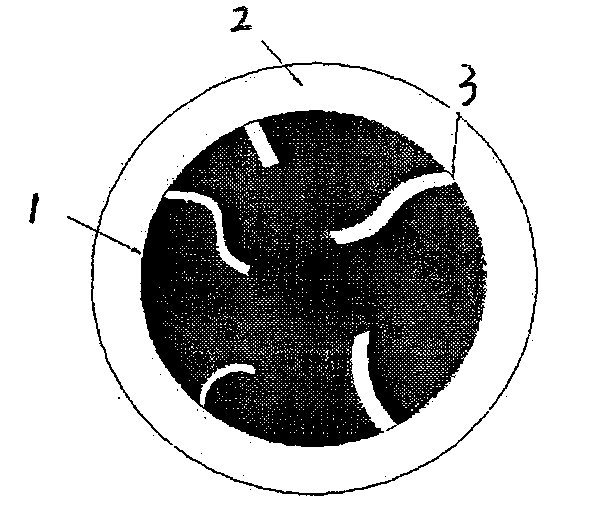
[0069] The core (magnetic particles)-shell (new catalyst) composite catalyst particles were prepared by pulsed laser sputtering deposition method or multi-target magnetron sputtering method, and γ-Fe 2 o 3 (Ferromagnetic particle core)-Gd 3-x Bi x SbO 7 (0.5≤x≤1) (photocatalyst shell), γ-Fe 2 o 3 (Ferromagnetic particle core)-Gd 3-x Y x SbO 7 (0.5≤x≤1) (photocatalyst shell), γ-Fe 2 o 3 (Ferromagnetic particle core)-In 3-x Bi x TaO 7 (0.5≤x≤1) (photocatalyst shell), SiO 2 (paramagnetic particle core)-Gd 3-x Bi x SbO 7 (0.5≤x≤1) (photocatalyst shell), SiO 2 (paramagnetic particle core)-Gd 3-x Y x SbO 7 (0.5≤x≤1) (photocatalyst shell), SiO 2 (paramagnetic particle core)-In 3-x Bi x TaO 7 (0.5≤x≤1) (photocatalyst shell), MnO (antiferromagnetic particle core)-Gd 3-x Bi x SbO 7 (0.5≤x≤1) (photocatalyst shell), MnO (antiferromagnetic particle core)-Gd 3-x Y x SbO 7 (0.5≤x≤1) (photocatalyst shell), MnO (antiferromagnetic particle core)-In 3-x Bi x TaO ...


PUM

PropertyMeasurementUnit
diameteraaaaaaaaaa
thicknessaaaaaaaaaa
particle diameteraaaaaaaaaa

Abstract

Magnetic-particle photocatalyst with a core-shell structure takes a ferromagnetism particle, a paramagnetism particle or a diamagnetism particle as a core, and photocatalyst as a shell. The ferromagnetism, paramagnetism or diamagnetism particles are gamma-Fe2O3, SiO2 or MnO particle respectively, and the photocatalyst is Gd3-xBixSbO7, Gd3-xYxSbO7 and In3-xBixTaO7 respectively, wherein the grain diameter of the gamma-Fe2O3, SiO2 and MnO is 80-2,000nm. Water-treatment is carried out on the photocatalyst in a magnetic field-photocatalytic system, and the periphery of a reaction system for water-treatment is provided with an alternating magnetic field generator with adjustable magnetic field intensity, wherein the range of the magnetic field intensity is 0-15T, and radiation light sources of the reaction system adopt a 300W xenon lamp and a 400W high-voltage mercury lamp; the ferromagnetism particle, paramagnetism particle and diamagnetism particle respectively account for 33+ / -10% in themagnetic-particle core for coating the photocatalyst, and are completely and uniformly dispersed in aqueous solution, thus the composite photocatalyst is uniformly distributed in the upper, middle and lower layers of the aqueous solution.

Description

technical field [0001] The invention relates to a photocatalyst, especially a magnetic particle photocatalyst with a core-shell structure, preparation and application, a magnetic composite material with a "magnetic particle core-photocatalyst shell" structure and a new nano-catalytic material Gd 3-x Bi x SbO 7 (0.5≤x≤1) and Gd 3-x Y x SbO 7 (0.5≤x≤1), and the gradient distribution of the composite photocatalytic material is obtained through a magnetic field, and the organic pollutants in the water body are removed by photocatalysis. Background technique [0002] The treatment of toxic and refractory organic substances (PTS) in water has always been a difficult and hot topic in the field of water treatment. PTS has the characteristics of high risk to human body and ecological environment. Therefore, developed countries have strict control standards for such pollutants. Since conventional biochemical treatment methods have poor removal effects (or almost no treatment eff...

Claims


Application Information

Patent Timeline
Patent Type & Authority Patents(China)
IPC IPC(8): B01J23/843B01J23/847B01J23/18B01J23/20B01J23/34H01F1/01C23C14/34C23C14/35C02F1/48C02F1/30C02F1/32C02F1/58C01B3/04C02F101/30
CPCY02E60/364Y02E60/36Y02W10/37
Inventor 栾景飞陈建辉李咏梅潘丙才
Owner NANJING UNIV
Why Eureka
Try Eureka