
Radio-frequency coil structure applied to low-magnetic field resonance imaging in thermal-ablation therapy

A technology of radio frequency coils and resonance imaging, which is applied in the fields of magnetic resonance measurement, application, medical science, etc., can solve the problems of small operating space, inconvenient operation, and inability to reserve, etc., and achieves the reduction of total cost, easy popularization and application, and simple structure Effect

Inactive Publication Date: 2010-06-30
陈武凡
View PDF0 Cites 4 Cited by
  • Summary
  • Abstract
  • Description
  • Claims
  • Application Information

AI Technical Summary

Problems solved by technology

[0003] At present, due to the restriction of the development level of effective temperature real-time monitoring technology, thermal ablation therapy technology cannot be widely used in the treatment of diseased tissues in various parts of the human body. It is achieved by extending the thermal ablation probe into the pelvic cavity from the human body cavity, but for other potential application sites, such as the brain, liver, prostate, breast, and musculoskeletal system, it is impossible to use the thermal ablation probe into the above-mentioned parts. Therefore, the approved clinical application site of ultrasonic concentrated energy therapy technology is limited to pelvic tissue
[0004] Among the existing intraoperative parameter monitoring technologies in the human body, magnetic resonance temperature-sensitive imaging technology is an important method to realize non-invasive real-time monitoring of target tissue temperature. Realized the real-time monitoring of the target tissue temperature of the human body during the operation, and organically combined the ultrasonic energy-concentrating technology with the magnetic resonance system. However, this combination was limited to the use of the high-field magnetic resonance system, and the process of applying the high-field magnetic resonance system Among them, since the high field is a horizontal field determined by its physical characteristics, the real-time temperature monitoring function of ultrasonic energy concentration can be realized without any change in the structure of the radio frequency coil. However, the defects of this monitoring method are: (1) radio frequency The coil cannot be made into an open structure, which is determined by the physical characteristics of the superconducting magnet. As a result, the operation space in the operation is very small, and the operation is quite inconvenient; (2) The cost of the high-field magnetic resonance system is expensive, And the cost of ultrasonic focused therapy quasi-device is also relatively high, making the overall cost too high, which limits the popularization of this combination therapy device
However, in the low-field magnetic resonance system, since its main magnetic field is a vertical field, the requirements for the structure of the radio frequency coil device are relatively high. When the radio frequency coil device is in use, the coil needs to enclose the human body. Or there are coil loops arranged on the back side, which makes it impossible to reserve space for thermal ablation probes (such as ultrasonic transducers used in ultrasonic focusing equipment) to provide barrier-free treatment channels; in addition, it is necessary to cooperate with various software and carry out Algorithm research can realize real-time monitoring of lesion target tissue
[0006] Due to the above-mentioned various technical problems, so far, there is no combined system of human tissue imaging and real-time temperature monitoring guided by a dedicated low-field magnetic resonance imaging system.

Method used


Image

  • Radio-frequency coil structure applied to low-magnetic field resonance imaging in thermal-ablation therapy
  • Radio-frequency coil structure applied to low-magnetic field resonance imaging in thermal-ablation therapy
  • Radio-frequency coil structure applied to low-magnetic field resonance imaging in thermal-ablation therapy

Examples


Embodiment Construction

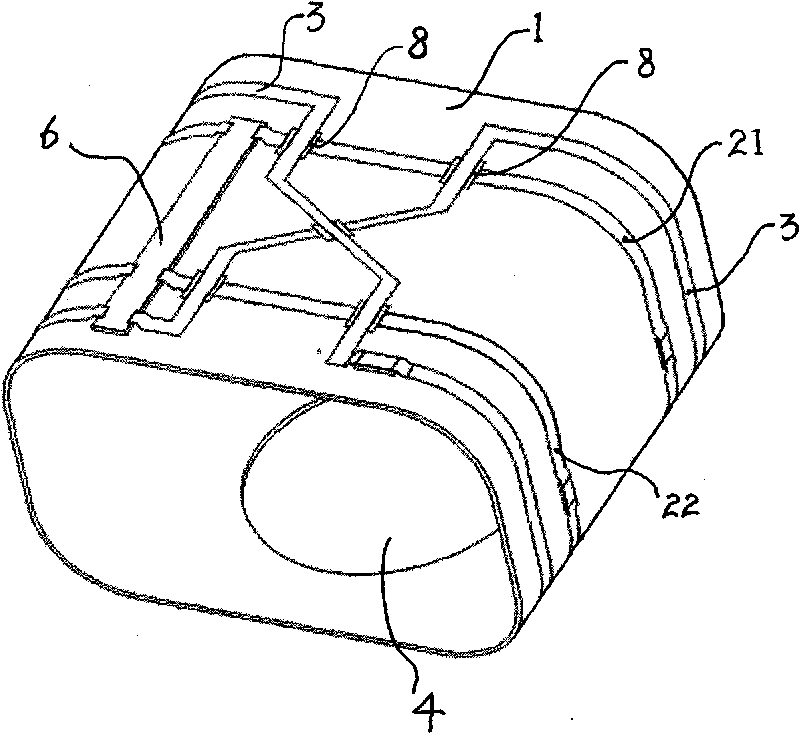
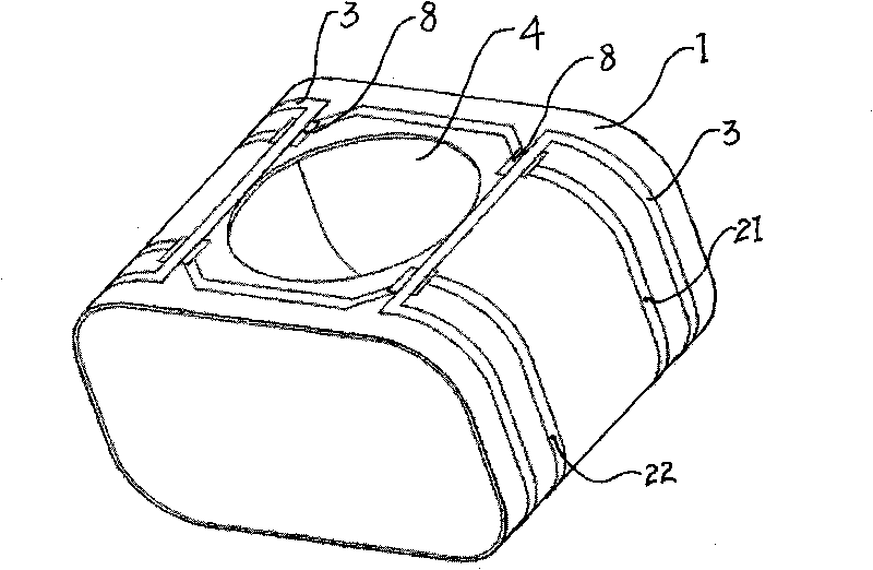
[0029] Such as figure 1 , 2 As shown, it is a radio frequency coil structure applied to low magnetic field resonance imaging of thermal ablation therapy according to the present invention, which includes a cylindrical support shell 1 made of non-magnetic insulating material and a coil arranged on the support shell 1. The coil adopts Copper material, non-magnetic insulating material is made of polyethylene material, the support shell 1 is a flat body shape, the support shell 1 is divided into two halves, and the connection between the two halves is a detachable connection; the coil It includes two solenoid coil units, and each solenoid coil unit is arranged in parallel. In this embodiment, each solenoid coil unit is provided with a solenoid closed coil, respectively for the solenoid closed Coils 21 and 22, the planes formed by the solenoid closed coils 21 and 22 are parallel to each other, and the distance between the solenoid closed coils 21 and 22 is 25 cm; Arranged side by...


PUM

PropertyMeasurementUnit
Diameteraaaaaaaaaa

Abstract

The invention relates to a radio-frequency coil structure applied to low-magnetic field resonance imaging in a thermal-ablation therapy, comprising a barrel-shaped support shell made of a nonmagnetic insulating material, and a coil arranged on the support shell, wherein the coil comprises at least two solenoid coil units which are arranged in parallel; a port used for transmitting a thermal-ablation function source and gathering the function on a pathological-change target tissue of a human body is arranged on the support face of the support shell, and the solenoid coil units are arranged around the port. The radio-frequency coil structure adopts the solenoid coil units, the port is arranged on the support shell and can be a thermal-ablation probe (such as an ultrasonic transducer for ultrasonic energy gathering equipment) for providing a barrier-free treating channel, and then the radio-frequency coil structure can realize the non-invasive real-time monitoring of human parameters in the thermal-ablation therapy after combining with relevant circuits and being applied to a magnetic resonance imaging system.

Description

technical field [0001] The invention belongs to the technical field of magnetic resonance imaging, and is a radio frequency coil structure capable of improving low-field MR imaging quality and precise measurement of intraoperative thermal ablation parameters. Background technique [0002] Thermal ablation therapy is an important part of the treatment of diseased tissues such as tumors. It is a method of locally increasing the temperature of diseased tissues (such as tumors) by means of radio frequency, microwave, ultrasonic concentration, laser, etc., so that the diseased tissues are coagulated and necrotic to achieve microscopic The purpose of invasive treatment. Therefore, the necrosis of lesion tissue is closely related to temperature. During the treatment process, it is necessary to monitor the temperature change of lesion target tissue in real time, so that the optimal energy release method can be used to release appropriate energy during thermal ablation treatment. [...

Claims


Application Information

Patent Timeline
IPC IPC(8): G01R33/34G01R33/36A61B5/055
Inventor 辛学刚冯前进冯衍秋韩继钧陈武凡
Owner 陈武凡
Learn More