Micro-drill for copper alloy processing and preparation method thereof

A copper alloy and micro-drilling technology, which is applied in metal material coating process, ion implantation plating, coating, etc., can solve the problems of low ionization rate, poor bonding force between film and micro-drilling substrate, and low film density , to achieve the effect of low friction coefficient, improved life and processing quality, and good film-base bonding force

Active Publication Date: 2012-07-04
NINGBO INST OF MATERIALS TECH & ENG CHINESE ACADEMY OF SCI
View PDF0 Cites 0 Cited by
  • Summary
  • Abstract
  • Description
  • Claims
  • Application Information

AI Technical Summary

Problems solved by technology

[0006] The technical problem to be solved by the present invention is to fundamentally solve the problem of low ionization rate in the deposition process, low density of the deposited film, low bonding force between the film and the micro-drill substrate due to the tip effect of the micro-drill tip during the current micro-drill coating. Poor and other issues

Method used


Image

  • Micro-drill for copper alloy processing and preparation method thereof
  • Micro-drill for copper alloy processing and preparation method thereof
  • Micro-drill for copper alloy processing and preparation method thereof

Examples


Embodiment 1

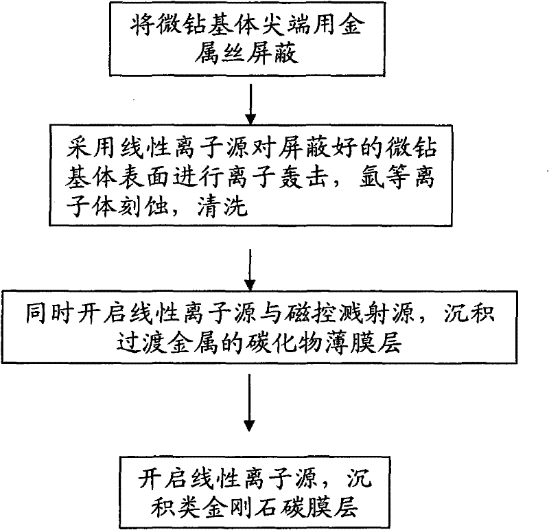
[0039] The coating machine used includes a vacuum chamber, a magnetron sputtering source, a linear ion source and a workpiece bracket with both revolution and rotation functions, and the workpiece bracket is installed inside the vacuum chamber.

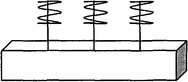
[0040] (1) Ultrasonic cleaning the micro-drill substrate in trichlorethylene, after drying, wind its tip with copper wire for shielding, and then install it on the workpiece bracket, arrange the magnetron sputtering source and linear ion source, so that the magnetron A sputtering source and a linear ion source surround the microdrill substrate.

[0041] (2) A chromium target made of simple chromium is installed on the magnetron sputtering source, and the vacuum chamber is evacuated to a pressure of 1.6×10 -5 After Torr, argon gas was introduced, the linear ion source was turned on, the negative bias voltage of the micro-drill substrate was adjusted to 200V, and the surface of the micro-drill substrate was bombarded with ions for 40 mi...

Embodiment 2

[0046] The coating machine used includes a vacuum chamber, a magnetron sputtering source, a linear ion source and a workpiece bracket with both revolution and rotation functions, and the workpiece bracket is installed inside the vacuum chamber.

[0047] (1) Ultrasonic cleaning the micro-drill substrate in absolute ethanol, after drying, wrap its tip with iron wire to shield, and then install it on the workpiece bracket, arrange the magnetron sputtering source and linear ion source, so that the magnetron sputtering The radiation source and the linear ion source surround the microdrill substrate.

[0048] (2) Install a titanium target made of elemental titanium on the magnetron sputtering source, and evacuate the vacuum chamber to a pressure of 2.0×10 -5 After Torr, argon gas was introduced, the linear ion source was turned on, the negative bias voltage of the micro-drill substrate was adjusted to 100V, ion bombardment was performed on the surface of the micro-drill substrate, a...


PUM


Abstract

The invention discloses a micro-drill for copper alloy processing and a preparation method thereof. The micro-drill comprises a micro-drill base body and a thin film deposited on the surface of the micro-drill base body; and the thin layer consists of three film layers; a transitional metal element film layer, a transitional metal carbide film layer and a diamond-like carbon film layer are arranged on the surface of the micro-drill base body in sequence from inside to outside. The preparation method comprises the step that: after the tip of the micro-drill base body is shielded by metal wires, the deposition of three film layers is carried out on the micro-drill base body by a linear ion source or / and a magnetic control sputtering source. The invention takes the shielding measures with metal wires on the tip of the high-speed steel micro-drill, and then carries out deposition of a plurality of layers of films, thus greatly improving the wear resistance and anti-adhesion performance, service life and processing quality of the micro-drill for copper alloy processing.

Description

technical field [0001] The invention relates to the field of micro-drills and preparation thereof, in particular to a micro-drill for copper alloy processing and a preparation method thereof. Background technique [0002] As microdrill diameters decrease and brittleness increases, deflection becomes the source of many problems. To control the brittleness of the micro-drill, it is necessary to balance the hardness and toughness of the micro-drill matrix. Generally speaking, high-speed steel micro-drills allow a certain degree of deflection and can withstand the corresponding bending force. However, the elastic deformation ability and low hardness of high-speed steel also reduce the wear resistance, thus limiting the micro-drilling. life. Therefore, improving the wear resistance of micro-drills has become an urgent problem to be solved. [0003] Generally, cemented carbide with high rigidity and high hardness is used as the micro-drill base material, which can prolong the l...

Claims


Application Information

Patent Timeline
Patent Type & Authority Patents(China)
IPC IPC(8): C23C14/35C23C14/04C23C14/06B32B9/04
Inventor 汪爱英孙丽丽张栋
Owner NINGBO INST OF MATERIALS TECH & ENG CHINESE ACADEMY OF SCI
Why Eureka
Try Eureka