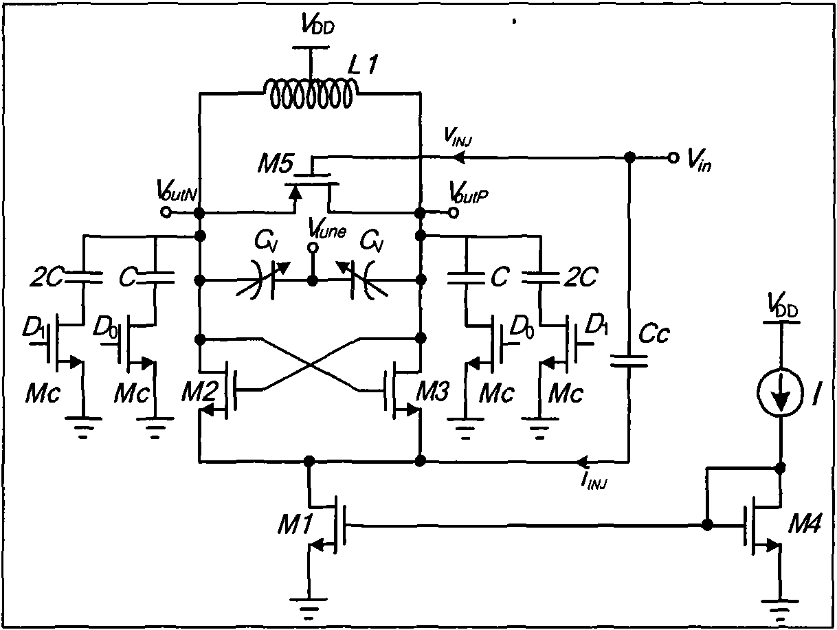
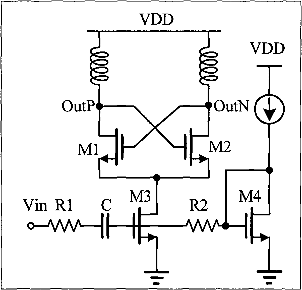
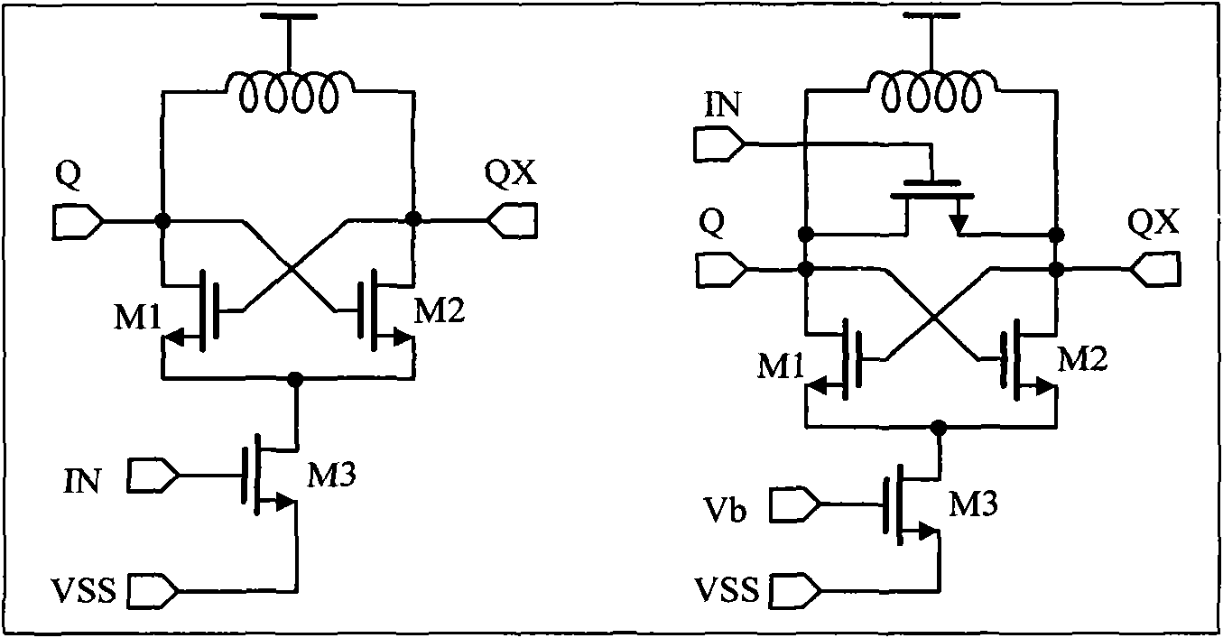
Injection locking frequency divider

An injection locking and frequency divider technology, applied in power oscillators, electrical components, etc., can solve the problems of limited operating frequency range of injection locking frequency dividers and affecting the stable operation of frequency dividers.

Inactive Publication Date: 2010-07-14
FUDAN UNIV
View PDF0 Cites 35 Cited by
  • Summary
  • Abstract
  • Description
  • Claims
  • Application Information

AI Technical Summary

Problems solved by technology

However, the disadvantage of the injection-locked frequency divider is that its operating frequency range is very limited, and the process deviation and temperature deviation in the actual chip manufacturing process will seriously affect the stable operation of the frequency divider

Method used


Image

  • Injection locking frequency divider
  • Injection locking frequency divider
  • Injection locking frequency divider

Examples


Embodiment 1

[0017] The injection-locked frequency divider of this structure is applied to the frequency synthesizer system of the MB-OFDM UWB radio frequency receiver in the 3.1GHz to 10.6GHz frequency band, Figure 4 Shown is a schematic diagram of the structure of the phase-locked loop in the frequency synthesizer, which consists of a frequency and phase detector, a charge pump, a loop filter, a voltage-controlled oscillator and a frequency divider chain. The frequency and phase detector detects the frequency difference and phase difference between the crystal oscillator (reference clock) and the output signal of the frequency divider, and converts the difference into a current signal through the charge pump, and the current flows into the loop filter A voltage signal is formed to adjust the frequency of the voltage-controlled oscillator until the frequency and phase difference detected by the frequency and phase detector are zero. In practical applications, the frequency divider chain ...


PUM


Abstract

The invention relates to an injection locking frequency divider used in the integrated circuit of a radio receiver, belonging to the technical field of integrated circuits of radio frequency radio receivers. The injection locking frequency divider is formed by an inductance-capacitance oscillator, a tuning circuit, a signal injection circuit and a current source biasing circuit, wherein the tuning circuit comprises a numerical control capacitor array tuner and a varactor tuner. Under the condition of no external input excitation, the inductance-capacitance oscillator self-oscillates by certain frequency. The tuning circuit tunes the self-oscillating frequency through varying the load of the resonant cavity of the oscillator. The signal injection circuit injects input signals into the resonant cavity of the oscillator to realize the traction and the locking of the self-oscillating frequency of the oscillator and to further the frequency halving of the input signals. Compared with the prior art, the invention has the advantages that the circuit can realize high working frequency under low power consumption and the working frequency range is wide.

Description

technical field [0001] The invention belongs to the technical field of radio frequency wireless receiver integrated circuits, and in particular relates to an injection locked frequency divider (Injection Locked Frequency Divider) applied in a wireless receiver integrated circuit. The frequency divider can be used in a frequency synthesizer system in an ultra-wideband wireless transceiver, and can realize frequency division of high frequency signals by two. Background technique [0002] With the development of modern information technology, the requirements for high data rate and large bandwidth of wireless communication technology are becoming more and more intense, which prompts people to continuously develop higher frequency band resources and study ultra-high frequency wireless communication technology. At the same time, under the inevitable trend of the development of modern integrated circuits to the direction of system chips, low power consumption design has become an ...

Claims


Application Information

Patent Timeline
Patent Type & Authority Applications(China)
IPC IPC(8): H03B19/00
Inventor 李宁尹江伟李巍任俊彦
Owner FUDAN UNIV
Why Eureka
Try Eureka