
Electromagnetic brake, friction piece thereof and friction piece manufacture method

A technology of electromagnetic brakes and friction parts, applied in elevators, hoisting devices, transportation and packaging, etc., can solve the problems of difficult control of spring adjustment, small wear amount, poor performance repeatability, etc., to improve safe working conditions and stabilize static and dynamic friction. coefficient, the effect of improving the contact wear resistance

Active Publication Date: 2010-08-11
HANGZHOU HUNING ELEVATOR PARTS CO LTD
View PDF1 Cites 18 Cited by
  • Summary
  • Abstract
  • Description
  • Claims
  • Application Information

AI Technical Summary

Problems solved by technology

[0004] 1. First of all, the friction plate adopts a fixed connection method. When the brake is applied, due to manufacturing and installation errors, the friction plate and the traction sheave often have poor contact. The two are not in complete surface contact, usually line contact or point contact. Contact, due to the small number of contact points between the two, the brake shoe and the brake wheel are not concentric or inclined, resulting in inconsistent clearance on both sides, insufficient braking force, reduced safety, and the wear of the friction plate is fast, and the wear The above-mentioned problems of the latter friction plate are more serious, and the control is extremely unstable; secondly, the friction plate is made of asbestos-free organic material, its friction coefficient is small, the instantaneous friction coefficient changes greatly, and the friction force is small during the braking process. Long, it is easy to generate a lot of heat and cause the temperature of the brake shoe to be high; in order to form a large braking force, a stronger spring force is needed, and the increase of the spring force will cause the electromagnetic force to be too large, which is easy The friction plate in direct contact with the traction sheave is severely worn, and a large piece falls off or burns
If the metal material is used to make the friction plate, in theory, although it can increase the friction force during braking, but: a. The metal friction plate and the metal traction sheave are in non-surface contact, and the wear of the friction plate is very Fast; b. When the metal friction plate and the metal traction wheel are in contact, a lot of noise will be generated, which cannot meet the mandatory standard requirements for traction machine brake noise
In order to reduce the noise generated when the two are in contact, it is necessary to reduce the gap between the moving plate and the static plate. With the reduction of the gap, the micro switch cannot detect the movement of the moving plate, so the existing traction machine brake Friction plates made of metal materials are not yet available
Finally, after the friction plate is worn out, it is very troublesome to replace or adjust the friction plate. It is difficult to adjust and control on site, the performance repeatability is poor, and the service life is reduced.
[0005] 2. The spring adjustment is difficult to control, and it is easy to be too tight, resulting in excessive braking force
When the voltage is too low or the line is faulty, the brake shoe sticks, and the gap between the electromagnet armatures is too large, it is easy to cause insufficient suction, or the gap between the electromagnet armatures is too small, resulting in too small suction stroke of the iron core, thus The brake cannot be opened, causing the brake to fail to reset normally
At the same time, due to low voltage or failure of brake components and adhesion of brake shoes, the response speed of electromechanical control switch measurement and clearance amount is slow in time, so that the brake cannot be released in time, resulting in slow brake release action. The existence of the gap makes the noise larger, and the noise coefficient has a mandatory standard requirement in the traction machine brake
[0006] 3. At present, the brake generally adopts a single-coil structure, and the single-coil structure has some technical defects. For this reason, Chinese Patent No. 200820106008.6 discloses a multi-coil plate brake, which is equipped with at least two circular coil windings in the base , and the base is placed with coils, although this patented technical solution has its advantages, but a whole piece of steel is processed by a CNC lathe to form a number of circular grooves to form the base, the processing is time-consuming and laborious, and the manufacturing cost is high
[0007] 4. At present, the switches used in the traction machine are all mechanical micro switches, which have technical defects such as low service life and unreliable work; moreover, the detection accuracy is low, such as the small gap between the moving plate and the static plate (such as 0.3mm), the existing mechanical micro switch can not detect
In addition, the current elevator traction machine brakes do not have the over-wear detection function of the friction plate, and the brake can only be manually disassembled to check whether the friction plate needs to be adjusted or replaced
[0008] Many of the above problems lead to relatively poor safety and stability of the brake, and it is difficult to meet the requirements of large braking torque, high component strength, small wear, low heating temperature of the friction plate, stable braking on the brake, low noise, flexible brake release and complete release. , small outline size and easy installation and other technical requirements will inevitably bring problems such as unstable control, complex structure and high manufacturing cost.

Method used


Image

  • Electromagnetic brake, friction piece thereof and friction piece manufacture method
  • Electromagnetic brake, friction piece thereof and friction piece manufacture method
  • Electromagnetic brake, friction piece thereof and friction piece manufacture method

Examples


Embodiment 1

[0099] 1. The production process of beryllium bronze friction plate: punching and blanking→stamping→aging hardening treatment, the details are as follows:

[0100] 1. Punching and blanking: select the soft QBe2.0 (C17200) beryllium bronze sheet with a thickness of 1.1mm and solution treatment, put it on an open tilting press and punch it into a square as a whole, and punch out four Circular through hole 41 and four square anti-off notches 42, four through holes 41 are evenly distributed around the center point of the square plate, four anti-off notches 42 are symmetrically arranged on two opposite edges, and anti-off notch 42 near the other two edges. see Figure 16 , 17 .

[0101] The soft beryllium bronze plate after solution treatment is blanked by an open tilting press to make the part flat and free of burrs, and to effectively prevent bending and cracking during stamping. In addition, beryllium bronze also has the advantages of being non-magnetic and not generating spar...

Embodiment 2

[0115] 1. The production process of beryllium bronze friction plate:

[0116] 1. Punching and blanking: use a beryllium bronze plate with a thickness of 1.1mm;

[0117] 3. Age hardening treatment: Heating in a vacuum furnace, keeping the temperature at 290°C for 4 hours.

[0118] 2. Die-casting molding: use beryllium bronze that has been stamped and aged as an insert, and position it in a preheated mold at 180°C. The mold retention time is 6.0s, the injection speed of aluminum water is 3.3m / s, and the injection force is 3500N , die-casting temperature 680 ℃ molding, holding time 4.5s, and then water cooling.

[0119] Other content of this embodiment is the same as that of Embodiment 1.

Embodiment 3

[0121] 1. The production process of beryllium bronze friction plate:

[0122] 1. Punching and blanking: use beryllium bronze plate with a thickness of 1.4mm;

[0123] 3. Age hardening treatment: Heating in a vacuum furnace, keeping the temperature at 260°C for 2.8 hours.

[0124] 2. Die-casting molding: use stamped and aged-treated beryllium bronze as an insert, position it in a preheated mold at 200°C, leave the mold for 7.5s, inject speed of aluminum water at 3.8m / s, and inject force at 3700N , die-casting temperature 660 ℃ molding, holding time 3.0s, and then water cooling.

[0125] Other content of this embodiment is the same as that of Embodiment 1.


PUM


Abstract

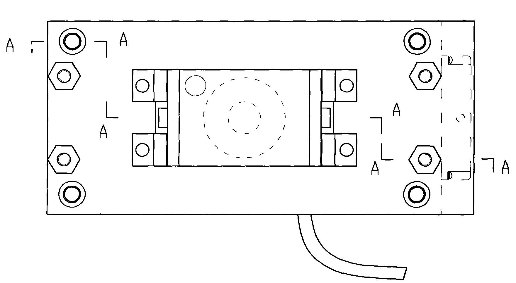
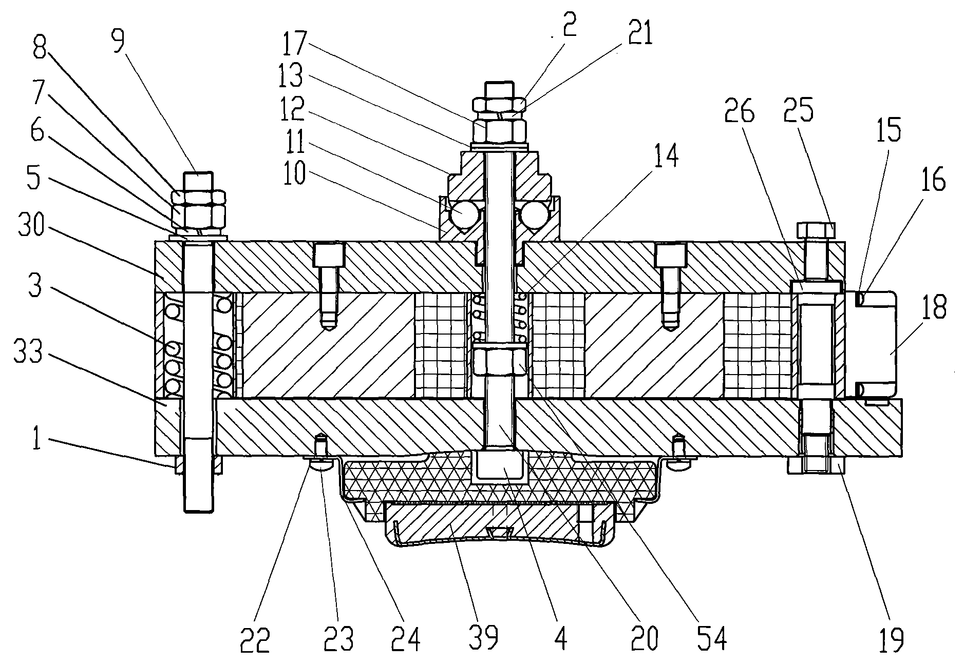
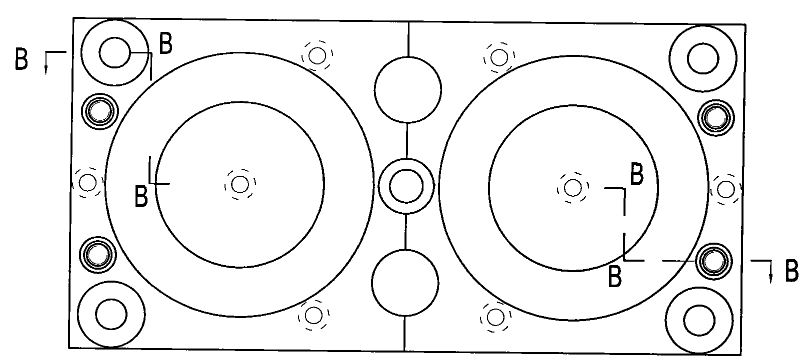
The invention discloses an electromagnetic brake, a friction piece thereof and a friction piece manufacture method. The electromagnetic brake comprises an iron core assembly, a magnetic roof assembly, a friction member and a manual brake release assembly, wherein the magnetic roof assembly comprises a magnetic roof; the manual brake release assembly comprises a bolt; the iron core assembly comprises an iron core bottom plate, an iron core outer ring, an iron core inner ring, a coil and a skeleton; the friction member is arranged on the outer side surface of the magnetic roof; the friction member and the magnetic roof are transversally positioned; the friction member is made of metal; the middle part of the outer side surface of the magnetic roof concaves inwards to form a spherical surface shape; the middle part of the outer side surface of the friction member convexes outwards to form the spherical surface shape which fits the inwards concave spherical surface part of the outer side surface of the magnetic roof, or, the middle part of the outer side surface of the magnetic roof outwards convexes to form the spherical surface shape, and the middle part of the outer side surface of the friction member concaves inwards to form the spherical surface shape which fits the outwards convex spherical surface part of the outer side surface of the magnetic roof. The electromagnetic brake has the advantages of big braking force, stable and reliable braking, convenient and simple assembly, energy saving, fast release, short time delay, low noise and the like.

Description

technical field [0001] The invention belongs to the technical field of elevator brakes, and in particular relates to an electromagnetic brake, a friction part thereof, and a manufacturing method of the friction part. Background technique [0002] The electromagnetic brake is an indispensable protection device for the safe operation of the elevator. It has two states of braking and reset. When the elevator runs abnormally, the system cuts off the power supply, and the electromagnet loses its electromagnetic force. Under the elastic force of the spring, the friction plate is pushed to contact. The traction sheave gradually stops the running elevator car and realizes the braking function, thus effectively preventing the elevator car from being dangerous due to abnormal movement. After the system achieves braking, the brake can be reset manually. When the system is energized and working normally, the electromagnet generates electromagnetic force, the friction plate releases the...

Claims


Application Information

Patent Timeline
Patent Type & Authority Applications(China)
IPC IPC(8): B66B5/00B66D5/02B66D5/30
Inventor 邹家春马新峰孟红星郎小东
Owner HANGZHOU HUNING ELEVATOR PARTS CO LTD
Learn More