Preparation method of photocatalysis microreactor

A technology of microreactor and photocatalysis, which is applied in chemical instruments and methods, physical/chemical process catalysts, chemical/physical processes, etc., can solve problems such as rough surface of microchannels, large fluid flow resistance, and difficult processing, and achieve Good photocatalytic effect, low equipment requirements and simple operation

Active Publication Date: 2010-08-18
NANTONG XIANGYANG OPTICAL ELEMENT +1
View PDF7 Cites 16 Cited by
  • Summary
  • Abstract
  • Description
  • Claims
  • Application Information

AI Technical Summary

Problems solved by technology

The microchannel system obtained by etching glass by wet etching is difficult to process, and it is isotropic etching, and it is difficult to obtain a smooth and deep microchannel system; the microchannel system formed by traditional ICP etching glass is difficult to etch Larger, and the surface of the etched microchannel is rough, the fluid flow resistance is relatively large, and the surface polishing technology is still difficult to achieve efficient polishing of the 3D microchannel system
The microfluidic channels prepared by combining organic materials with embossing method have poor aging resistance and poor sealing effect when working in the environment of ultraviolet lamps, and are prone to leakage after long-term use

Method used


Image

  • Preparation method of photocatalysis microreactor
  • Preparation method of photocatalysis microreactor
  • Preparation method of photocatalysis microreactor

Examples


Embodiment 1

[0027] A preparation method for a photocatalytic microreactor, comprising the following steps:

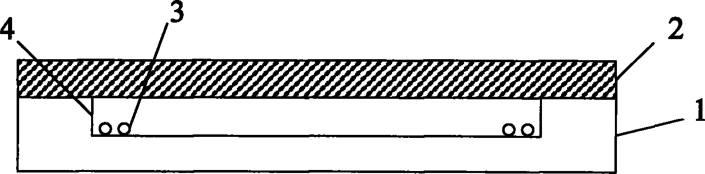
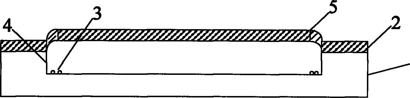
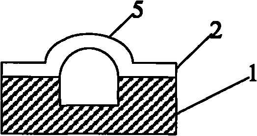
[0028] The first step is to etch on the silicon wafer to form a specific silicon microfluidic pattern, and locally place an appropriate amount of high-temperature air release agent on both ends of the silicon microfluidic groove or at a specific position. The high-temperature air release agent is calcium carbonate or titanium hydride powder , the pattern of the silicon microfluidic channel is set according to the graphic needs of the microreactor,

[0029] In the second step, anodically bond the above-mentioned silicon wafer and borosilicate glass wafer in air or vacuum. It can be Pyrex7740 glass or other borosilicate glass, so that the above-mentioned silicon microfluidic channel on the silicon wafer forms a sealed cavity, and is heated in the air to 760 ° C ~ 900 ° C, for example, the temperature can be selected as 800 ° C, 830 ° C , 850°C, 880°C, 890°C, keep warm for 5-10 minut...

Embodiment 2

[0039] A preparation method for a photocatalytic microreactor, comprising the following steps:

[0040] In the first step, utilize Si micromachining process to etch microfluidic channel shallow grooves on Si wafers (such as 4-inch wafers), and the silicon wafer used can be a silicon wafer of standard thickness, such as a silicon wafer with a thickness of 500 microns. The depth of the shallow groove is 10-200 microns, such as 15 microns, 30 microns, 40 microns, 60 microns, 95 microns, 132 microns, 150 microns, 180 microns, and the aspect ratio is usually less than 2, such as 1.5, 1 , 0.8, 0.5, 0.2, 0.1, 0.05, 0.02, the micromachining process of the pattern structure on the Si wafer is a wet etching process, or a dry inductively coupled plasma (ICP) etching process, reactive ion etching One, preferably a wet etching process, such as etching with TMAH solution, the pattern can be striped or serpentine, and adjusted as needed.

[0041] The second step is to place an appropriate a...

Embodiment 3

[0049] A preparation method for a photocatalytic microreactor, comprising the following steps:

[0050] The first step is to use Si micromachining technology to etch microchannel shallow grooves on a 4-inch Si wafer. The silicon wafer used can be a silicon wafer with a standard thickness and a thickness of 500 microns. The depth of the shallow grooves is 60 microns. The runner groove is a strip groove with a diameter of 2 mm, and the length of the groove is 3 cm. The micromachining process of the pattern structure on the Si wafer is a wet etching process, and the used etching solution is a TMAH solution with a concentration of 10% and a temperature of 80 degrees Celsius,

[0051] In the second step, chemically pure calcium carbonate powder is placed in a shallow tank with a particle size of 5 microns and a mass of 30 micrograms.

[0052] The 3rd step, above-mentioned Si disc and Pyrex7740 glass disc (a kind of brand of borosilicate glass, the U.S. Corning-corning company prod...


PUM

PropertyMeasurementUnit
depthaaaaaaaaaa

Abstract

The invention discloses a preparation method of a photocatalysis microreactor, comprising the following steps of: forming a specific silicon micro-flow slot pattern on a silicon wafer by etching; locally placing the proper amount of high-temperature gas releasing agent at both ends or specific positions of a micro-flow slot; carrying out anodic bonding on the silicon wafer and a glass wafer in air or vacuum to enable the micro-flow slot on the silicon wafer to form a seal cavity body, and heating to 760-900 DEG C in the air and carrying out heat preservation for 5-10 min, wherein the high-temperature gas releasing agent releases gas to generate positive pressure after being heated to enable melted glass corresponding to the seal cavity body to be in a circular tube shape; cooling the melted glass to form a glass micro-flow channel; preparing an inlet and an outlet on the glass micro-flow channel; removing the decomposition residues of the high-temperature gas releasing agent; coating a photocatalyst on the inner tube wall of the glass micro-flow channel to form a thermal forming glass photocatalysis microreactor. In the invention, the cylindrical glass micro-flow channel is adopted to serve as the shell of the reactor, and thereby, a larger specific surface area is provided, the cost is low and the photocatalysis reaction efficiency is high.

Description

technical field [0001] The preparation method of the microreactor of the present invention particularly relates to a preparation method of a photocatalytic microreactor. Background technique [0002] Photocatalytic oxidation has many unique features and has extremely strong oxidation ability. Among them, titanium dioxide, as a photocatalyst, has many advantages such as non-toxicity, stability, reusability, no photocorrosion phenomenon, and no secondary pollution. At present, the commonly used titanium dioxide with photocatalytic effect is Degussa P25 nano-TiO2. Photocatalysis is often suspended in the reagent required for catalysis. Suspension photocatalysis requires subsequent separation and other processes, which increases the complexity and cost of the process. Therefore, the efficiency of macroscopic photocatalysis is low. [0003] At present, the microfluidic system is mainly used in the field of sensors and biochips, and is in a stage of vigorous development. Photoc...

Claims


Application Information

Patent Timeline
Patent Type & Authority Applications(China)
IPC IPC(8): B01J19/00B01J19/12B01J35/02
Inventor 尚金堂陈波寅徐超张迪
Owner NANTONG XIANGYANG OPTICAL ELEMENT
Why Eureka
Try Eureka