Optical fiber probe of fluorescent optical fiber temperature sensor and preparation method thereof

A temperature sensor, fiber optic probe technology, used in thermometers, thermometers with physical/chemical changes, instruments, etc., can solve the problems of limited temperature measurement range, inability to measure temperature, poor measurement repeatability, etc., to increase service life and use. Reliability, preventing the influence of external interference light, and facilitating extraction and processing

Active Publication Date: 2012-06-06
西安和其光电科技股份有限公司
View PDF0 Cites 0 Cited by
  • Summary
  • Abstract
  • Description
  • Claims
  • Application Information

AI Technical Summary

Problems solved by technology

[0003] Among them, the fiber grating temperature sensor based on the principle of light reflection and the fiber optic Faber temperature sensor based on the principle of optical interference are both demodulated based on wavelength changes to obtain temperature change information. The fiber optic demodulator is complex to manufacture and has high performance requirements for the discrete devices used. The manufacturing cost is high, and the sensor itself is also greatly affected by other factors such as stress, requiring more complicated compensation techniques to obtain practical temperature information
[0004] The temperature measurement technology based on optical fiber Raman scattering, which combines OTDR and other technologies, is technically more difficult and more costly; based on thermal radiation technology, it is suitable for high temperature measurement, but its measurement accuracy is low and the application field is very narrow. Usually, it can only be realized Non-contact measurement; optical fiber thermometer based on light absorption technology, the measurement error is too large, the measurement repeatability is poor, and it is greatly affected by the change of light intensity, so it is difficult to be practical
[0005] For the above-mentioned types of optical fiber temperature sensors, the optical fiber materials used for signal transmission are usually single-mode optical fibers used in communication, and the working temperature can only be -50 ~ 85 ° C, which cannot withstand high temperatures, which limits its temperature measurement range. , the optical fiber probe package is usually made of metal or ceramic materials, the package size is large, it is impossible to realize the temperature measurement in a narrow range area, and it is impossible to reach into the object or equipment to realize the temperature measurement of a local point

Method used


Image

  • Optical fiber probe of fluorescent optical fiber temperature sensor and preparation method thereof
  • Optical fiber probe of fluorescent optical fiber temperature sensor and preparation method thereof
  • Optical fiber probe of fluorescent optical fiber temperature sensor and preparation method thereof

Examples


preparation example Construction

[0033] The preparation method of the optical fiber probe of the fluorescent optical fiber temperature sensor comprises the following steps:

[0034] 1] Insert one end of the optical fiber into the connector and extend it, and fix it with glue;

[0035] 2] After fixing, cut off all the light-transmitting optical fibers protruding from the connector, and grind and polish the cut-off end face of the light-transmitting optical fibers;

[0036] 3] Coating reflective resin on the other end of the optical fiber that is not inserted into the connector to form a reflective resin layer, and coating phosphor powder on the surface of the reflective resin layer to form a fluorescent layer;

[0037] 4] Put the light-transmitting optical fiber not inserted into the connector into the protective sleeve, the sleeve is passed to the connector, and epoxy resin is applied between the connector and the connector to fix it. The end face of the protective sleeve near the fluorescent layer is The ve...

Embodiment 1

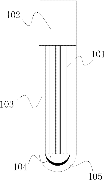
[0041] In this embodiment, a bundle of multi-component glass optical fibers 101 is used. One bundle contains approximately 10 to 1000 single glass optical fibers, the core diameter of a single glass optical fiber is 20 to 50 μm, the numerical aperture is 0.3 to 0.8, and the length is 0 to 100 m. 101 is covered with a polytetrafluoroethylene tube 103, one end of the optical fiber bundle 101 is added with a connector 102, fixed with glue, ground and polished, the other end of the optical fiber bundle 101 is coated with silicone resin 104, and the surface of the silicone resin 104 is coated with fluorescent powder 105. Cut off the casing at one end of the fluorescent powder 105 at a point 5-10 mm longer. Use a sealing machine to seal the sleeve tube at one end of the fluorescent powder 105. The advantage of this embodiment is that a bundle of multi-core glass optical fibers is used, which is resistant to high temperature and bending, and the demodulated signal is not affected by ...

Embodiment 2

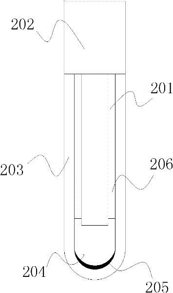
[0043]In this embodiment, a quartz optical fiber 201 is used. The core diameter of the quartz optical fiber 201 is 200-400 μm, the numerical aperture is 0.1-0.3, and the length is 0-100 m. The outer diameter of the quartz optical fiber 201 is coated with acrylic resin 206. Add a connector 202 at one end, fix it with glue, grind and polish it, peel off the coating layer about 5mm at the other end, grind and polish the end face of the optical fiber, glue silicone resin 204 on the end face of the optical fiber, and coat the surface of the silicone resin 204 with fluorescent light Powder 205. Dot 353ND glue or other epoxy resin around the optical fiber with the coating stripped off, insert a black glass tube 203 with an inner diameter of 0.6-1.0 mm and an outer diameter of 0.8-1.5 mm, and seal one end of the black glass tube 203 . The advantage of this embodiment is that a quartz optical fiber is used, which is easy to process and can withstand high temperature, and the fluorescen...


PUM

PropertyMeasurementUnit
pore sizeaaaaaaaaaa
lengthaaaaaaaaaa
reflectanceaaaaaaaaaa

Abstract

The invention provides an optical fiber probe of a fluorescent optical fiber temperature sensor and a preparation method thereof. The optical fiber probe has the advantages of simple structure, small volume, light weight, high measuring precision, large measuring range, good repeatability, long service life, chemical corrosion resistance, electromagnetic interference resistance, and the like. Theoptical fiber probe of the fluorescent optical fiber temperature sensor comprises a light transmission optical fiber, one section of the light transmission optical fiber is fixedly arranged in a connector through epoxy resin, and the other section of the light transmission optical fiber is arranged in a protection sleeve. The end face of the optical fiber arranged in the protection sleeve is provided with a reflecting resin layer, and a fluorescent layer is arranged on the reflecting resin layer. The protection sleeve and the connector are connected in a sealing mode through the epoxy resin.

Description

technical field [0001] The invention relates to an optical fiber probe and a preparation method, in particular to an optical fiber probe for a fluorescent optical fiber temperature sensor and a preparation method, and belongs to the technical field of optical fiber sensing. Background technique [0002] The existing optical fiber temperature measurement technology is mainly based on the principles of light reflection, light absorption, light interference, light scattering, and thermal radiation. [0003] Among them, the fiber grating temperature sensor based on the principle of light reflection and the fiber optic Faber temperature sensor based on the principle of optical interference are both demodulated based on wavelength changes to obtain temperature change information. The fiber optic demodulator is complex to manufacture and has high performance requirements for the discrete devices used. The manufacturing cost is high, and the sensor itself is also greatly affected by...

Claims


Application Information

Patent Timeline
Patent Type & Authority Patents(China)
IPC IPC(8): G01K11/32
Inventor 张文松朱香平赵卫
Owner 西安和其光电科技股份有限公司
Why Eureka
Try Eureka