High-performance direct current amplification device for acquiring biological electric signals

A bioelectric signal, DC amplification technology, applied in applications, medical science, sensors, etc., can solve the problems of unsatisfactory anti-interference ability, small signal dynamic range, low dynamic range, etc., achieving significant economic and social benefits, high circuit Integrated, high dynamic range effects

Active Publication Date: 2010-11-24
EDAN INSTR
View PDF0 Cites 34 Cited by
  • Summary
  • Abstract
  • Description
  • Claims
  • Application Information

AI Technical Summary

Problems solved by technology

The dynamic range will be lower, and clinically, the amplitude of the ECG signal of the patient may exceed ±5mV. For the ECG signal with a large amplitude, this circuit will cause cut-off distortion
Therefore, it is difficult to meet the needs of actual clinical tests
[0004] 2. The amplifying circuit generally includes multiple links such as a buffer stage, a three-op-amp instrument amplifier stage, an RC time constant circuit stage, a low-pass filter circuit stage, and a main gain stage. The wiring is complicated, and each link will increase noise, so the system noise level is difficult. control, generally speaking, the equivalent input noise level reaches above 15uVpp
Secondly, there are many devices used, and the weak signal traces on the printed circuit board are generally very long, so they are easily affected by the radiation of space interference sources.
Anti-interference ability is not ideal
[0005] 3. Due to the large gain of the amplifier and the small dynamic range of the signal, in clinical applications, a small signal disturbance (such as patient muscle contraction, electrode movement) will easily cause the amplifier to saturate
Baseline recovery will take a very long time due to the time constant circuit
This is a fatal flaw in the field of clinical ECG detection. Doctors will not be able to bear the problems of amplifier saturation and baseline drift caused by long-term baseline drift.
[0006] 4. PACE pulse detection problem
The PACE signal may be very large (up to 700mVpp in extreme cases). Due to the small dynamic range of the AC amplifier circuit, the output of the op amp will be saturated. In addition to the influence of charging and discharging of the time constant circuit, the baseline will have a large drift.
Therefore, it is difficult for the AC amplifier architecture to effectively detect the PACE signal
[0007] 5. The DC component of the signal source and the AC signal close to the DC signal are lost
Since the parameters of the RC time constant circuit are fixed (the typical value of the time constant is 3.2 seconds), the AC signal below 0.05HZ will be discarded by the AC amplifier circuit, which cannot reflect the low-frequency signal containing important information of the signal source, which will bring ST in the field of ECG testing. It is difficult to provide doctors with accurate and undistorted waveforms
[0008] 6. High power supply voltage is not conducive to low power consumption
In order to ensure the dynamic range and gain, this kind of AC amplifier often adopts a relatively high power supply voltage, which is not good for the power consumption control of the board, and is contrary to the industry development trend of low power consumption and low voltage.

Method used


Image

  • High-performance direct current amplification device for acquiring biological electric signals
  • High-performance direct current amplification device for acquiring biological electric signals
  • High-performance direct current amplification device for acquiring biological electric signals

Examples


Embodiment Construction

[0028] Below in conjunction with what is shown in the accompanying drawings, the present invention will be further described in detail:

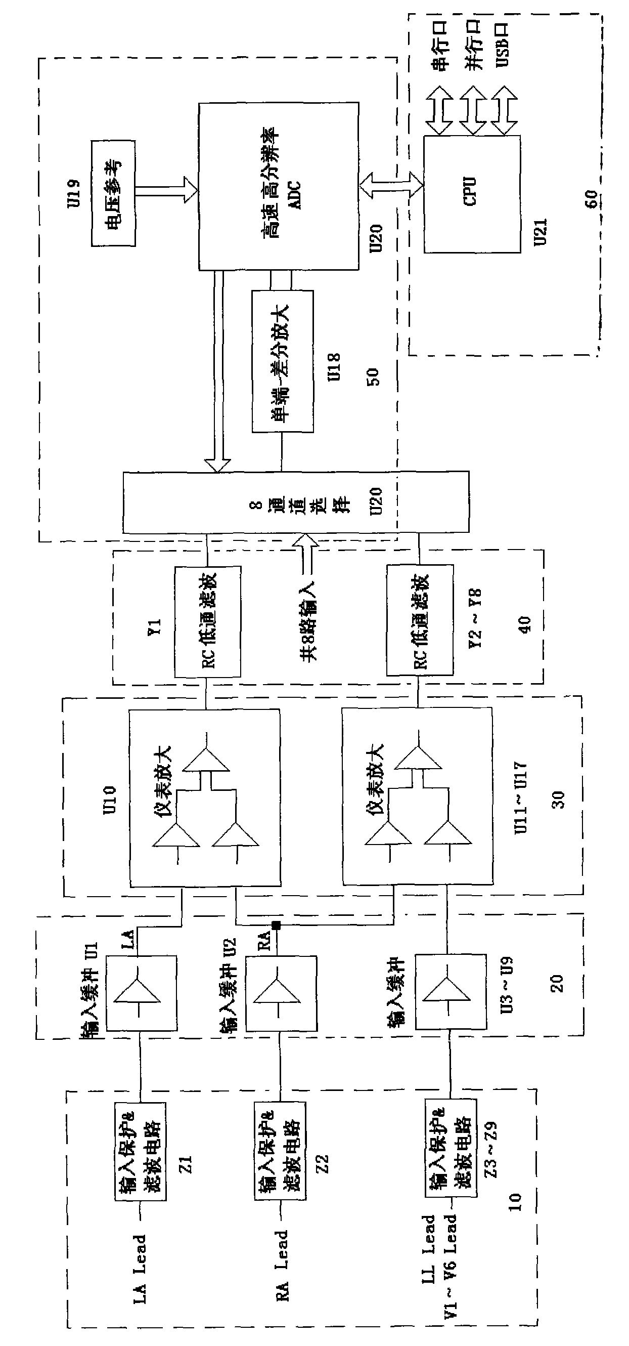
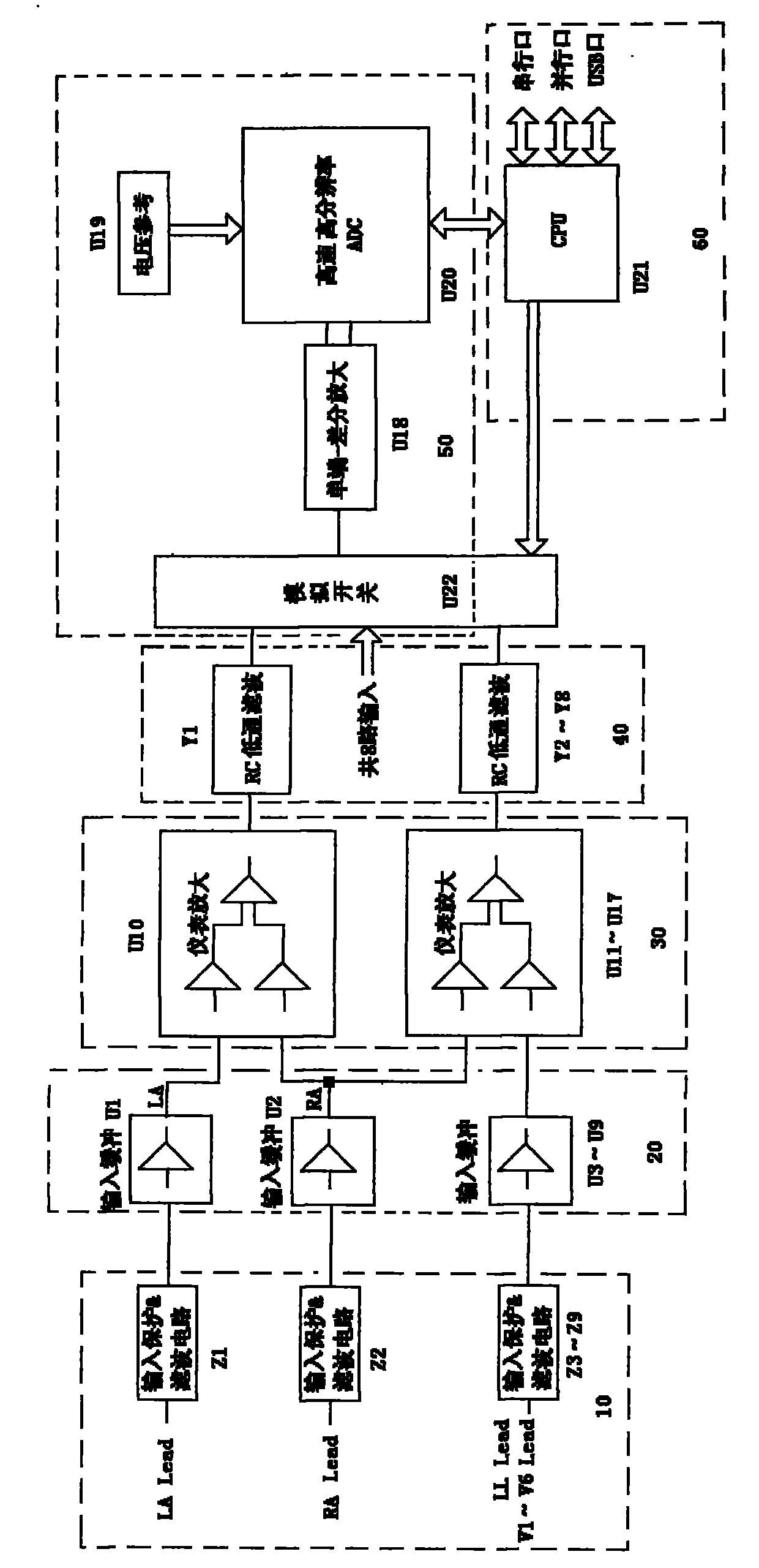
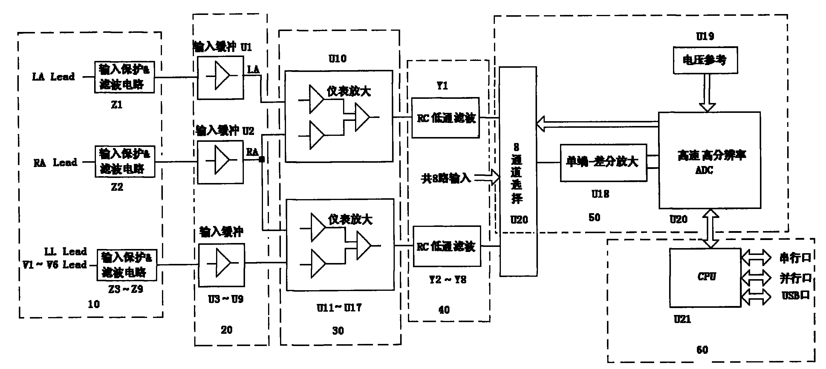
[0029] like figure 1 and figure 2 As shown, a high-performance DC amplification device for bioelectrical signal acquisition includes an input protection / filter circuit 10, an input buffer circuit 20, an instrument amplifier circuit 30, an RC low-pass filter circuit 40, and an analog-to-digital conversion and peripheral circuit 50. And CPU60, after the input protection / filtering circuit 10 collects the bioelectrical signal and inputs it to the input buffer circuit 20, then the instrument amplifier circuit 30, the RC low-pass filter circuit 40, the analog-to-digital conversion and the peripheral circuit 50 are sequenced; the analog-to-digital conversion is controlled by the CPU60 And peripheral circuit 50 works.

[0030] Among them, the input protection & filter circuit filter circuit 10 has nine routes, Z1-Z9, and each route is composed of...


PUM


Abstract

The invention discloses a high-performance direct current amplification device for acquiring biological electric signals, which comprises an input protection / filter circuit, an input buffer circuit, an instrument amplifying circuit, an RC low-pass filter circuit, an analog-digital conversion and peripheral circuit and a CPU connected in sequence, wherein the input protection / filter circuit acquires the biological electric signals and inputs the biological electric signals into the input buffer circuit, and then the biological electric signals pass through the instrument amplifying circuit, the RC low-pass filter circuit and the analog-digital conversion and peripheral circuit in turn; and the CPU controls the analog-digital conversion and peripheral circuit to work. The high-performance direct current amplification device performs impedance conversion on the biological electric signals first, then amplifies the signals, inhibits common-mode signals, and filters high-frequency noise, and a single-end transfer differential amplifier performs secondary amplification on the biological electric signals, so the indexes such as the noise, the common-mode rejection ratio and the like of the signals after analog-digital conversion reach a very high level; besides, a base line is very stable, the signal input dynamic range is large and is difficult to saturate, and simultaneously required devices are fewer, and the reliability of the high-performance direct current amplification device is improved.

Description

technical field [0001] The invention relates to the field of electronic measurement and control technology, in particular to the field of detection of weak bioelectrical signals, and in particular to a high-performance direct-current amplification device for collecting bioelectrical signals. Background technique [0002] At present, the detection of weak bioelectrical signals is carried out under the condition of strong background interference and the presence of patient polarization voltage. The bioelectrical signal on the surface of the human body is only at the millivolt level, while the polarization voltage can often reach hundreds of millivolts. The 50 / 60HZ power frequency interference that space couples to the human body is more likely to be as high as tens of volts. In addition, the patient is a very complex signal source, and its equivalent output impedance and polarization voltage are often in a changing state. How to obtain clean bioelectrical signals accurately ...

Claims


Application Information

Patent Timeline
Patent Type & Authority Applications(China)
IPC IPC(8): A61B5/0428A61B5/04A61B5/308
Inventor 向小飞胡寻桥孔令峰邱四海
Owner EDAN INSTR
Why Eureka
Try Eureka