Catalytic conversion method for converting low-quality heavy oil into light clean fuel oil

A catalytic conversion method and catalytic conversion technology, applied in the direction of multi-stage series refining and cracking process treatment, vacuum distillation, etc., can solve the problems of increased energy consumption and loss of catalytic raw materials, and achieve energy saving and high particle separation efficiency Effect

Active Publication Date: 2010-12-01
CHINA PETROLEUM & CHEM CORP +1
View PDF7 Cites 18 Cited by
  • Summary
  • Abstract
  • Description
  • Claims
  • Application Information

AI Technical Summary

Problems solved by technology

However, this method will carry a lot of light components in the vacuum residue, thus losing good catalytic raw materials
At the same

Method used


Image

  • Catalytic conversion method for converting low-quality heavy oil into light clean fuel oil
  • Catalytic conversion method for converting low-quality heavy oil into light clean fuel oil
  • Catalytic conversion method for converting low-quality heavy oil into light clean fuel oil

Examples


Embodiment 1

[0070] Example 1 The method provided by the present invention is used to remove solid particles in the catalytic oil slurry.

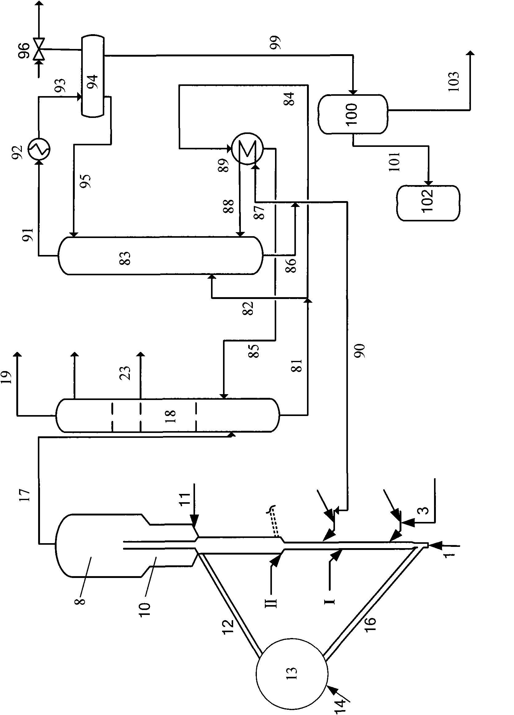
[0071] The process flow is attached figure 1 As shown, the catalytic oil slurry from the bottom of the catalytic cracking fractionation tower enters the vacuum fractionation tower, and carries out vacuum distillation under the condition of operating conditions. Particulate Catalytic Slurry Heavy Fraction. The properties of the catalytic oil slurry are shown in Table 1, and the operating conditions and results are shown in Table 2.

[0072] As can be seen from Table 2, under the same feed amount of catalytic oil slurry in Comparative Examples and Examples, the separation effect of light oil slurry is equivalent, but the energy required for heating is significantly reduced.

Embodiment 2

[0074] Example 2 illustrates the catalytic conversion method provided by the present invention for converting the inferior heavy oil feedstock provided by the present invention into light clean fuel oil.

[0075] Use as attached figure 1 In the process shown, the raw material of inferior heavy oil is inferior hydrogenated residue, and its properties are shown in Table 3. The catalytic cracking catalyst used in the catalytic conversion reactor is a conventional catalytic cracking catalyst, the commercial brand is MLC-500 and the self-made catalyst GZ-1, and its properties are listed in Table 4. See Table 5 for operating conditions, Table 6 for slurry properties, and Table 7 for catalytic conversion results.

[0076] The preparation method of catalyst GZ-1 is briefly described as follows:

[0077] 1), 20gNH 4 Cl was dissolved in 1000g water, and 100g (dry basis) crystallization product ZRP-1 zeolite (produced by Qilu Petrochemical Company Catalyst Factory, SiO 2 / Al 2 o 3 ...


PUM


Abstract

The invention discloses a catalytic conversion method for converting low-quality heavy oil into light clean fuel oil, which comprises: (1), introducing low-quality raw material oil into a catalytic cracking reactor having two reaction areas for performing a cracking reaction, wherein the reaction conditions in the catalytic cracking reactor ensure the catalytic wax oil obtained by the reaction is12 to 60 weight percent based on the weight of the low-quality raw material oil; (2) introducing the catalytic wax oil carrying catalyst particles into a reduced-pressure distillation tower, and separating a catalytic wax oil light fraction from the top of the tower; (3) hydrogenating the catalytic wax oil light fraction to obtain hydrogenated catalytic wax oil; and (4) circulating the hydrogenated catalytic wax oil to a catalytic conversion device for further reaction to obtain a light fuel oil target product. The method provided by the invention has the advantages that: due to the catalyticcracking of the low-quality heavy oil raw material, the catalytic wax oil yield is high, and the dry gas yield and cock yield are low; after solid particle removal and hydrogenation, the obtained catalytic wax oil can be introduced back to the catalytic cracking device for recycling, so the light oil yield of the whole process is increased by 5 to 15 percent and oil slurry yield is reduced; and thus, the high-efficiency use of oil resources is realized.

Description

technical field [0001] The invention relates to a catalytic conversion method of heavy hydrocarbon oil, more specifically, relates to a catalytic conversion method of converting inferior heavy oil raw material into light hydrocarbon oil fuel in the largest amount. Background technique [0002] The quality of crude oil is getting worse with the continuous increase of crude oil extraction, mainly manifested in the increase of crude oil density, viscosity, heavy metal content, sulfur content, nitrogen content, colloid and asphaltene content and acid value. At present, the price difference between low-quality crude oil and high-quality crude oil is also increasing with the shortage of oil resources, resulting in more and more attention to low-priced low-quality crude oil extraction and processing methods, that is, to increase as much as possible from low-quality crude oil. The yield of light oil has brought huge challenges to traditional crude oil processing technology. [0003...

Claims


Application Information

Patent Timeline
IPC IPC(8): C10G55/06C10G7/06
Inventor 张执刚许友好谢朝钢张久顺陈昀朱根权龚剑洪鲁维民
Owner CHINA PETROLEUM & CHEM CORP
Why Eureka
Try Eureka