

Preparation process and device of nano-particle reinforced bimetal composite
A nanoparticle, composite technology
- Summary
- Abstract
- Description
- Claims
- Application Information
AI Technical Summary
Problems solved by technology
Method used
Image

Examples
Embodiment 1
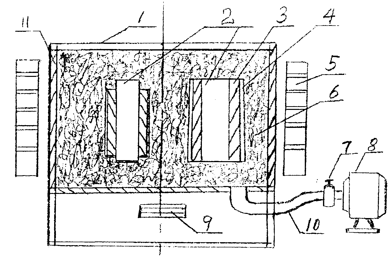
[0042] Example 1: figure 1 This equipment is a vacuum induction melting equipment. The equipment consists of box cover 1, workpiece 2, coating 3, protective coating 4, frequency conversion induction heater 5, manufacturing sand 6, vacuum pump valve 7, vacuum pump 8, vibrator 9, pipeline 10, box 11, frequency conversion induction heating The vibrator 5 is installed outside the box body 11, and the vibrator 9 is installed on the bottom or side of the box body 11. The vibrator 9 is mechanical vibration or ultrasonic vibration, and the frequency of the variable frequency induction heater 5 can be segmented from 500Hz to 200kHz. Stepless adjustment, the vacuum pump 8 is installed on any side of the box body 11, and is connected with the vacuum pump valve 7 and the vacuum pump 8 through the pipeline 10.
[0043] When the work starts, first set the mass percentage content as 20%Cr; 10%Ni, 2.5%Mo, 1.3%Si, 2.4%Mn, 1.8B%, 0.5%MgO, 0.4%CaF 2 , 0.3% C, 0.2% Nb, 0.5% CeO 2 , the balance...
Embodiment 2
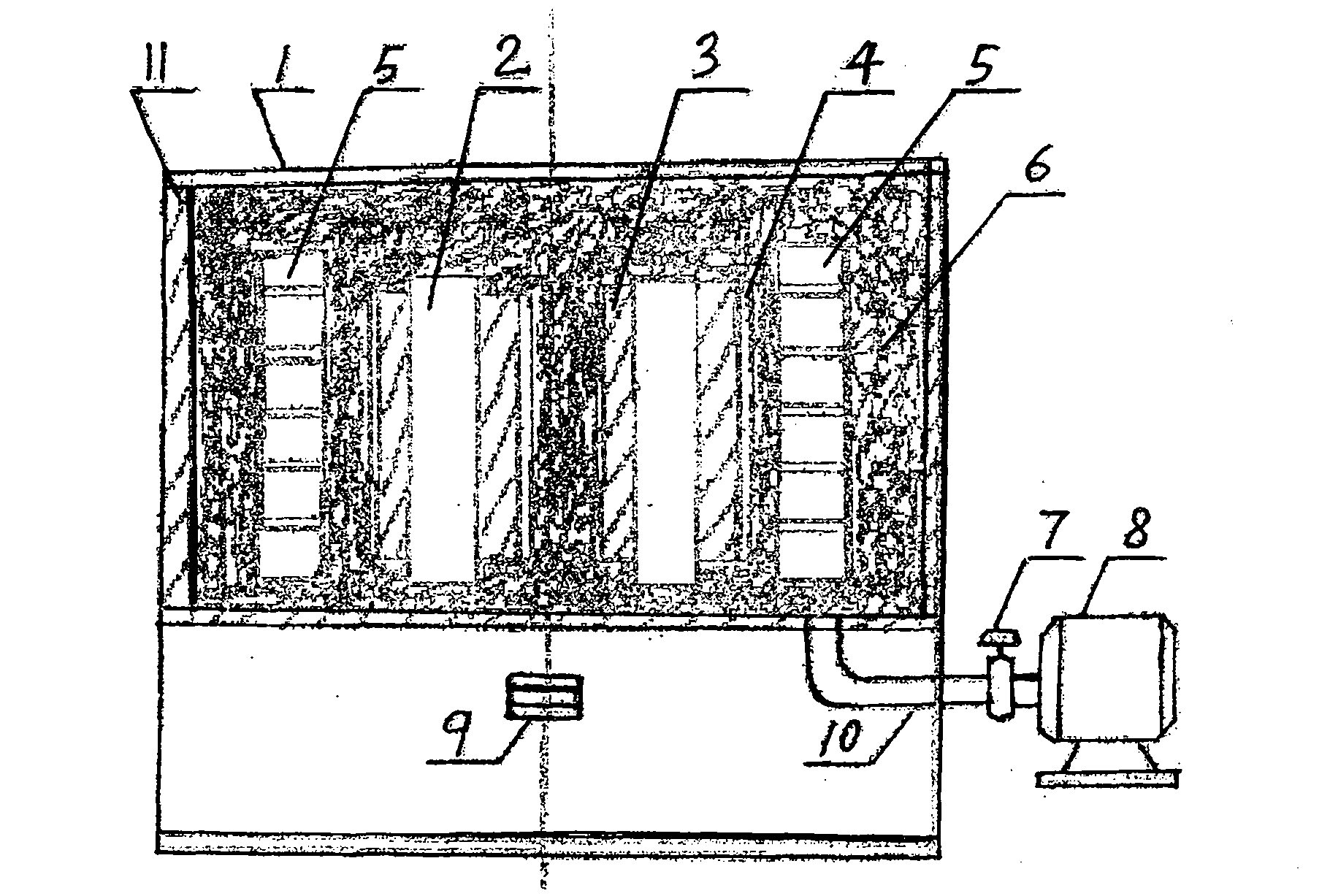
[0044] Example 2: In figure 2 in, with figure 1 The difference is that the frequency conversion induction heater 5 is installed in the box body 11 .
[0045] At the beginning of the work, the mass percentage content is 15%Cr; 15%Ni, 3%Mo, 1.8%Si, 2.4%Mn, 2.0B%, 0.7%MgO, 0.5%CaF 2 , 0.47% C, 0.38% Nb, 0.4% Y 3 o 2 , 0.2% Co, and the balance is Fe. Put the raw materials of the above components into the mixer according to the ratio of the ingredients and mix them thoroughly. The mixing time is 4 hours to prepare an alloy powder, and then add it to the alloy powder of the above ingredients WC nanoparticles with a mass percentage content of 35% are prepared into a mixed alloy powder containing WC nanoparticle reinforcement, or prepared into a micro-nano hybrid alloy powder containing WC nanoparticle reinforcement through a stirring ball milling process in a stirring ball mill; Add 6% gasoline rubber solution adhesive to the above-mentioned alloy powder to prepare an alloy past...
Embodiment 3
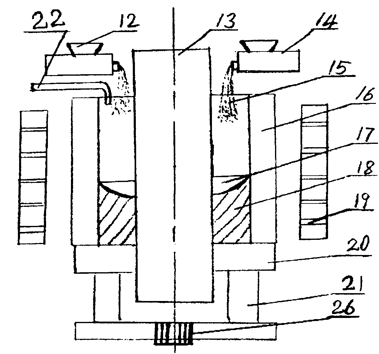
[0047] Example 3: image 3 It is a vacuum induction cladding equipment. and figure 1 and figure 2 The difference is: the equipment consists of particle feeders 12 and 14, workpiece 13, alloy powder 15, molding die 16, molten pool 17, bimetallic composite and cladding layer 18, frequency conversion induction heater 19, bottom plate 20 , a lifting device 21, an inert gas delivery pipe 22 and a vibrator 26, wherein the number of particle feeders 12 and 14 is 1 to 8, installed on the upper part of the molding die 16, and the frequency conversion induction heater 19 is installed on the top of the molding die 16 Externally, the bottom plate 20 and the lifting device 21 are installed on the lower part of the molding die 16, the vibrator 26 is installed on the lower part or the upper part or the side of the molding die, the inert gas delivery pipe 22 is installed on the upper part of the molding die 16, and the molding die is divided into double open and close metal Water-cooled c...
PUM
 Abstract
Description
Claims
Application Information