Thermal circulation system cooled by liquefied natural gas and flow

A technology of thermal cycle system and power cycle, applied in liquefaction, charging system, refrigeration and liquefaction, etc., can solve the problems of insufficient cold utilization of LNG, decreased system efficiency, and yet to achieve zero CO2 emissions.

Inactive Publication Date: 2010-12-22
INST OF ENGINEERING THERMOPHYSICS - CHINESE ACAD OF SCI
View PDF4 Cites 30 Cited by
  • Summary
  • Abstract
  • Description
  • Claims
  • Application Information

AI Technical Summary

Problems solved by technology

But this method is cold for LNG Insufficient utilization, combined cycle efficiency improvement of less than 1%
But this cycle can only separate and recover about 80% of the CO produced by the combustion process 2 , has not yet achieved CO 2 zero emission
[0017] It can be seen that

Method used


Image

  • Thermal circulation system cooled by liquefied natural gas and flow
  • Thermal circulation system cooled by liquefied natural gas and flow
  • Thermal circulation system cooled by liquefied natural gas and flow

Examples


no. 1 example

[0110] Referring to Table 2-2 for the thermal performance of the cycle of the first embodiment, the main thermal performance parameters of the cycle of the first embodiment are given under the equilibrium conditions shown in Table 2-1.

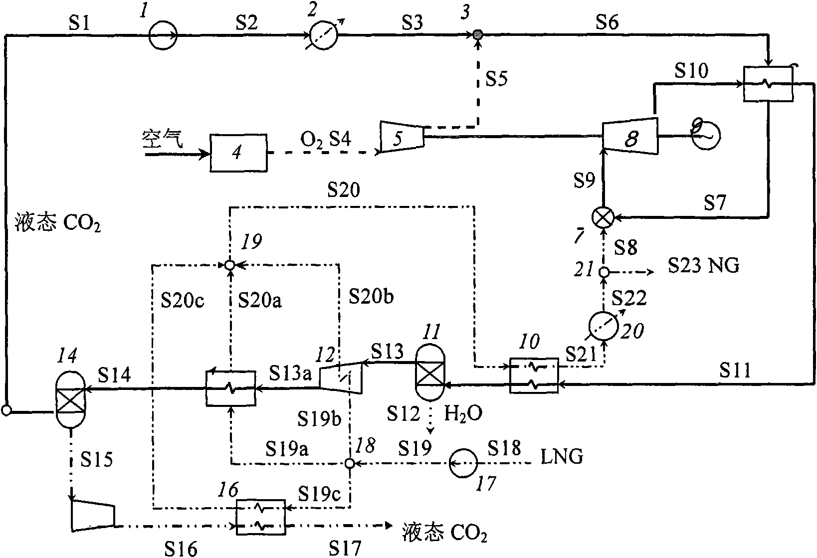
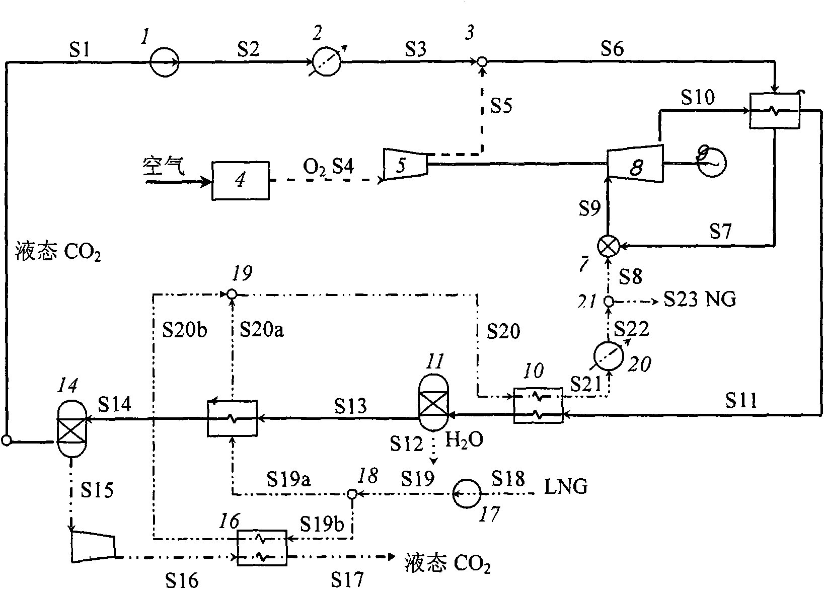
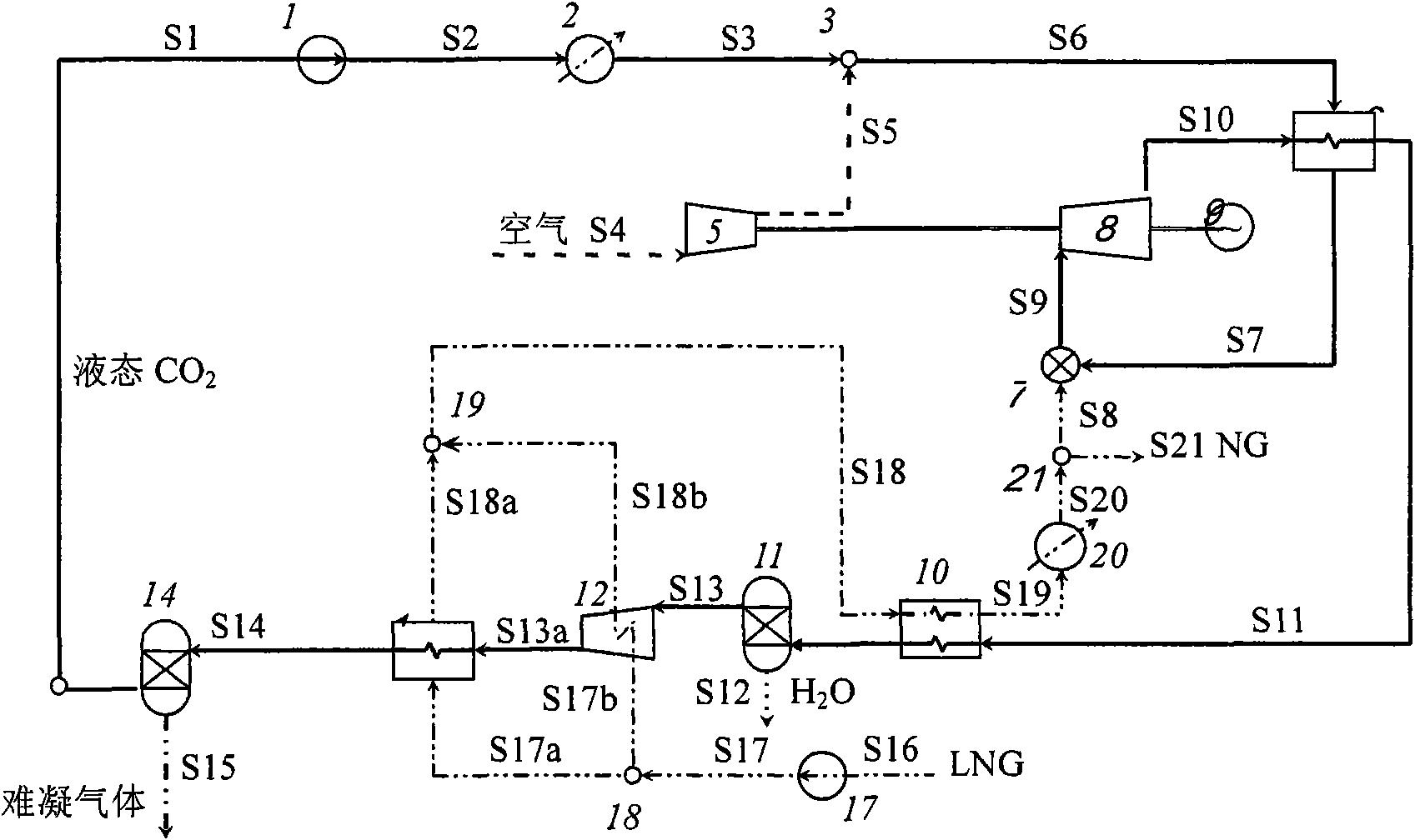
[0111] See the second embodiment figure 2 , the main part of the present invention is based on CO 2 It is a regenerative Brayton-Rankine composite power cycle and a liquefied natural gas (LNG) gasification unit as the main circulating working fluid. Where: 1-Liquid CO 2 Booster pump; 2-evaporator; 3-working medium mixer; 4-air separation unit; 5-compressor; 6-regenerator; 7-combustion chamber; 8-gas turbine; 9-generator; 10 -LNG vaporizer; 11-water separator; 13-CO 2 Condenser; 14-CO 2 Separator; 15-Tail gas compressor; 16-Tail gas heat exchanger; 17-LNG booster pump; 18-LNG splitter; 19-LNG mixer;

[0112] The connection in the above system is a known technology, and the present invention will not be described in detail here.

[0113] ...


PUM


Abstract

The invention discloses a thermal circulation system cooled by liquefied natural gas and a flow. The thermal circulation system consists of a Brayton-Rankine power circulation unit and an LNG liquefaction unit, wherein the power circulation is realized by using a CO2 circulating medium and coupled by the backheating-combustion-expansion work doing flow of backheating Brayton circulation and the condensation-liquid compression pressurization process of Rankine circulation and the backheating unit is used for realizing the effective heat integration in the circulation; meanwhile, through system coupling, the LNG liquefaction unit is used as a cold source of the power circulation to provide a cold source of which the temperature is always below ambient temperature for the condensation process of the power circulation, so the CO2 generated in a combustion reaction is separated from the circulation without consuming mechanical power. The thermal performance of the thermal circulation system is improved greatly. At the same time, the system realizes zero CO2 discharge while applying a pure oxygen combustion technique. Thus, the system has higher economy and environmental-protection performance and a promising engineering application prospect.

Description

technical field [0001] The invention relates to a cooling system that will utilize liquefied natural gas (LNG) Power generation technology and carbon dioxide (CO 2 ) The regenerative Brayton-Rankine composite thermodynamic cycle system and process combined with emission reduction and separation technology. Background technique [0002] The technology related to the present invention mainly comprises utilizing LNG to cool Power generation technology and CO 2 Emission reduction and separation technologies, the development status and system characteristics of their respective technologies are as follows: [0003] 1. Using LNG to cool power generation technology [0004] The sulfur contained in natural gas is precipitated and separated in solid form during the cryogenic process of liquefaction. Therefore, LNG does not contain sulfide and is a safe and clean energy source. The natural gas liquefaction process requires a large amount of energy for compression and cooling ...

Claims


Application Information

Patent Timeline
IPC IPC(8): F02C3/20F02C7/224F02C6/00F02C7/12F25J1/00F25J3/04F25D3/10F02G5/00
CPCY02T10/166Y02E20/16Y02T10/12
Inventor 张娜刘猛诺姆里奥
Owner INST OF ENGINEERING THERMOPHYSICS - CHINESE ACAD OF SCI
Why Eureka
Try Eureka