Coherent demodulation device for CPT atomic clock

A coherent demodulation and atomic clock technology, applied in the field of atomic clocks, can solve the problems such as the difficulty of taking into account the noise performance and volume of external circuits, affecting the stability of the CPT atomic frequency scale, increasing the power consumption and volume of discrete circuits, etc., to meet the requirements of small signal detection. and high precision requirements, low power consumption, and the effect of avoiding quantization errors

Active Publication Date: 2012-03-07
WUHAN INST OF PHYSICS & MATHEMATICS CHINESE ACADEMY OF SCI
View PDF1 Cites 0 Cited by
  • Summary
  • Abstract
  • Description
  • Claims
  • Application Information

AI Technical Summary

Problems solved by technology

The existing three methods have their own disadvantages. The first method has high requirements on the acquisition speed and accuracy of ADC and DAC, and also has high requirements on the reference clock of ADC and DAC. It needs a special clock distribution chip to provide clock for the circuit. And a special control chip is required as the control interface, which increases the power consumption and volume of the discrete circuit, which is not conducive to the miniaturization of the CPT atomic clock. At the same time, this method has higher requirements on the processing capability of the microcontroller, and the processing algorithm and digital circuit The introduced noise has a great influence on the modulation and demodulation effect, and will directly affect the stability of the CPT atomic frequency standard; the feedback control circuit of the second method is complex to adjust and has poor flexibility; the switch demodulation method in the third method generally uses field effects The tube controls the switch, and the noise performance and volume of the external circuit are difficult to balance

Method used


Image

  • Coherent demodulation device for CPT atomic clock
  • Coherent demodulation device for CPT atomic clock
  • Coherent demodulation device for CPT atomic clock

Examples


Embodiment Construction

[0031] Below in conjunction with accompanying drawing, the present invention will be described in further detail:

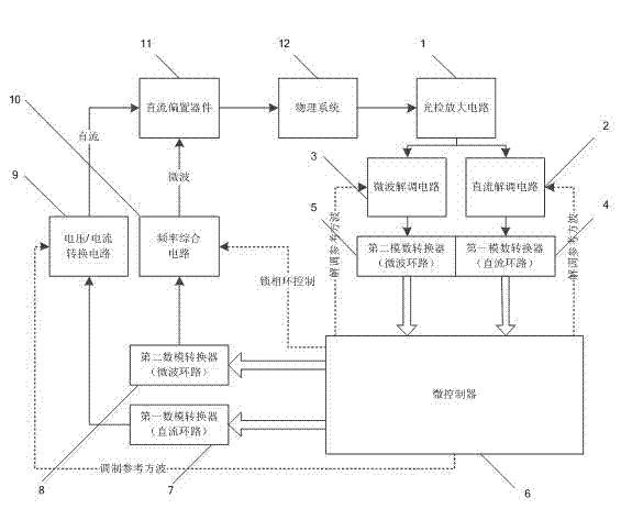
[0032] according to figure 1 It can be seen that a coherent demodulation device for CPT atomic clocks consists of a photodetector amplifier circuit 1, a DC demodulation unit 2, a microwave demodulation unit 3, a first analog-to-digital converter (DC loop) 4, a second analog Digital converter (microwave loop) 5, microcontroller 6, first digital-to-analog converter (DC loop) 7, second digital-to-analog converter (microwave loop) 8, voltage / current conversion circuit 9, frequency synthesis A circuit 10, a DC bias device 11, and a physical system 12 are composed. The CPT atomic frequency standard servo circuit mainly completes the control and locking of two loops, one is the laser frequency stabilization loop, and the other is the microwave frequency stabilization loop. Correspondingly, each loop contains independent modulation and demodulation devices . The conne...


PUM


Abstract

The invention discloses a coherent demodulation device for a CPT atomic clock, which comprises two paths of modulation and demodulation units, and a digital control circuit and an analog demodulation circuit are adopted to realize high-precision coherent demodulation. A microcontroller is connected with a voltage / current conversion circuit and a frequency synthesis circuit respectively through two paths of digital to analog converters; the microcontroller outputs modulation reference square waves to the voltage / current conversion circuit to realize DC loop modulation; the microcontroller controls frequency synthesis circuit connection to realize microwave loop modulation; the output of the voltage / current conversion circuit and the output of the frequency synthesis circuit are connected with the input end of a VCSEL of a physical system through DC bias devices; photo-signals output by the physical system pass through an optical test amplifying circuit and are connected to a DC demodulation circuit and a microwave demodulation circuit; and demodulation results are respectively input to the microcontroller through an analog to digital converter. The device has the advantages of small volume, low power consumption and high signal to noise ratio. The device-based atomic clock indexes have reached the level of the internationally best commercial small CPT atomic clock.

Description

technical field [0001] The present invention relates to the technical field of atomic clocks, in particular to a coherent demodulation device for coherent population trapping (CPT, Coherent Population Trapping) atomic clocks. It can be applied to miniaturized commercial atomic clock systems, and has broad application prospects in the fields of low power consumption, small size, high precision, and high stability frequency standards. Background technique [0002] The CPT atomic clock is a new type of atomic clock, which is realized by using the phenomenon of coherent population confinement, which saves the microwave cavity of the traditional atomic clock, and is a kind of all-optical atomic clock. Compared with traditional atomic clocks, it has the advantages of small size, low power consumption, and fast startup. Combined with micro-electromechanical system (MEMS, Micro Electromechanical System) technology, it can achieve a volume of several cubic centimeters, button battery...

Claims


Application Information

Patent Timeline
Patent Type & Authority Patents(China)
IPC IPC(8): H03L7/26
Inventor 邓威张奕云恩学顾思洪
Owner WUHAN INST OF PHYSICS & MATHEMATICS CHINESE ACADEMY OF SCI
Why Eureka
Try Eureka