Automobile driven by thermoacoustic engine

A thermoacoustic engine and automobile technology, which is applied to machines/engines, mechanisms that generate mechanical power, mechanical equipment, etc., can solve the problems of limited thermal energy, low power, and no thermoacoustic engine gas compression system without moving parts. , to achieve the effect of reducing fuel consumption and reducing consumption

Inactive Publication Date: 2011-01-12
肖家华
View PDF2 Cites 5 Cited by
  • Summary
  • Abstract
  • Description
  • Claims
  • Application Information

AI Technical Summary

Problems solved by technology

But this thermoacoustic device still has the following disadvantages: one, in this patent document, the power of the automobile is still driven by the exhaust gas of a gasoline or diesel engine, and the generation of these exhaust waste heat depends on the main engine of the automobile; two, the thermoacoustic device The generated electric energy is used in the auxiliary system of the automobile, which uses the exhaust gas generated by the internal combustion engine as the energy source of the thermoacoustic device, and the output heat energy of the exhaust gas is very limited, especially in today's increasingly strict emission standards for automobile exhaust. Under the strict premise, using automobile exhaust to heat the high temperature section of the thermoacoustic device, the heat energy it can provide is extremely limited
Therefo

Method used


Image

  • Automobile driven by thermoacoustic engine
  • Automobile driven by thermoacoustic engine
  • Automobile driven by thermoacoustic engine

Examples


Embodiment 1

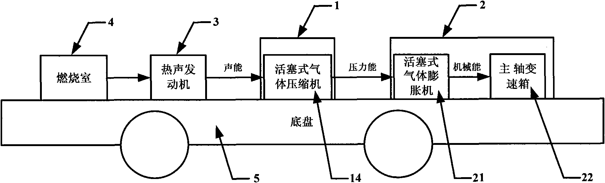
[0054] Such as figure 1 Shown is a schematic diagram of a car driven by a thermoacoustic engine whose acoustic energy conversion system is a diaphragm gas compressor. The car driven by a thermoacoustic engine includes a thermoacoustic engine and a chassis, wherein the thermoacoustic engine is placed on the chassis. The car powered by the thermoacoustic engine also includes a combustion chamber, a piston gas compressor, a gas expander, and a spindle gearbox, the combustion chamber, the piston gas compressor, the piston gas expander, the spindle transmission The tanks are placed on the chassis, and the combustion chamber is connected to the input end of the thermoacoustic engine, the output end of the thermoacoustic engine is connected to the input end of the piston gas compressor, and the piston gas compressor The output end of the compressor is connected to the input end of the piston gas expander, the output end of the piston gas expander is connected to the input end of the ...

Embodiment 2

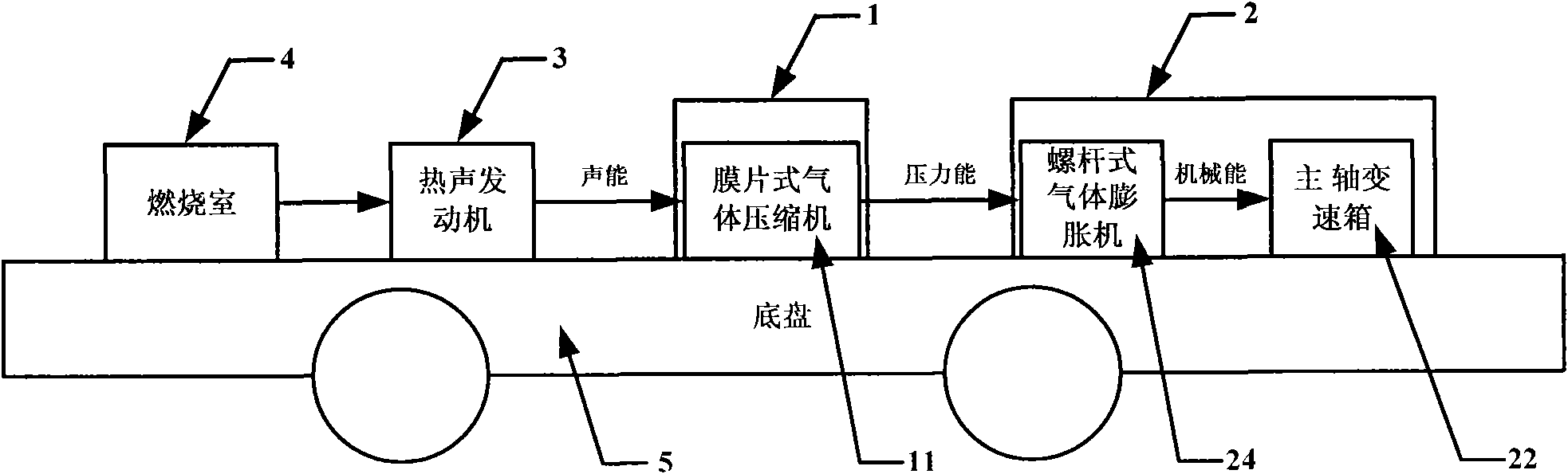
[0057] The piston gas compressor in Embodiment 1 is replaced by a diaphragm gas compressor, and the piston gas expander is replaced by a screw gas expander, such as figure 2 Shown, others are with embodiment 1.

Embodiment 3

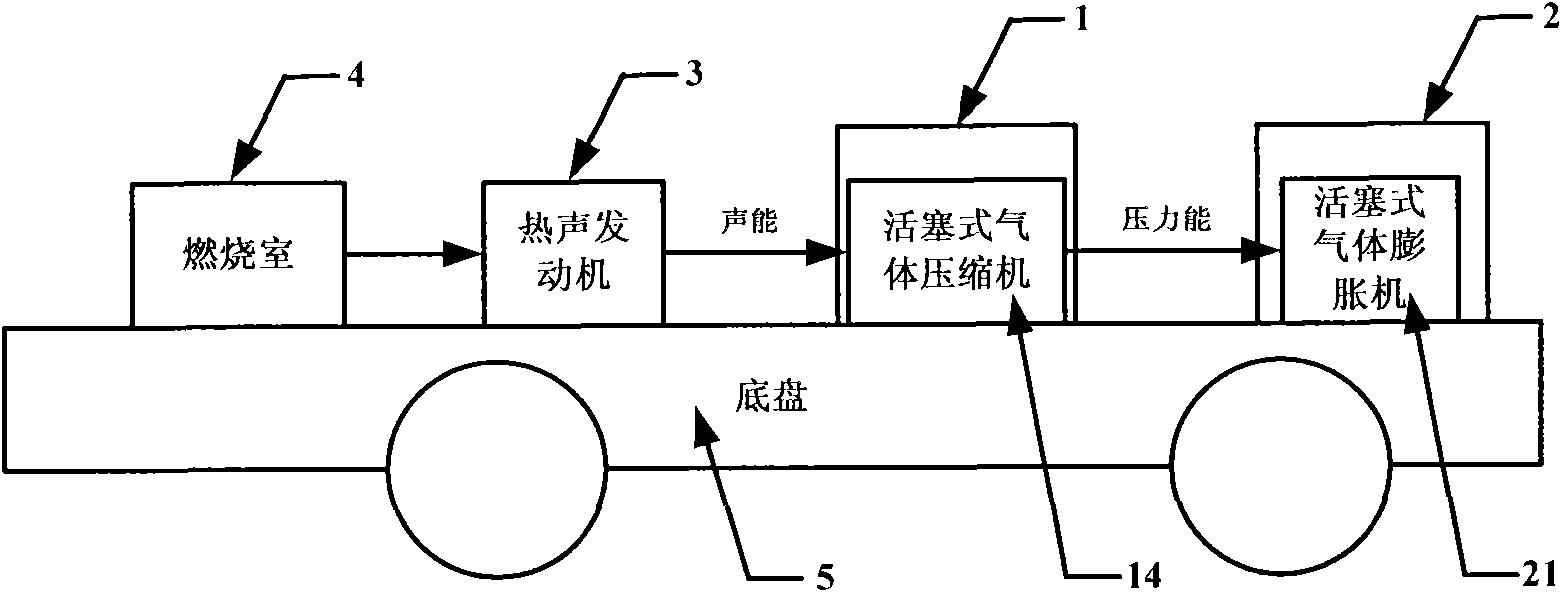
[0059] Such as image 3 Shown is a schematic diagram of a car driven by a thermoacoustic engine whose acoustic energy conversion system is a piston gas compressor. The car driven by a thermoacoustic engine includes a thermoacoustic engine and a chassis, wherein the thermoacoustic engine is placed on the chassis, and the thermoacoustic engine The vehicle powered by the acoustic engine also includes a combustion chamber, a piston gas compressor, and a piston gas expander, the combustion chamber, the piston gas compressor, and the piston gas expander being placed on the chassis, and The combustion chamber is connected to the input end of the thermoacoustic engine, the output end of the thermoacoustic engine is connected to the input end of the piston gas compressor, and the output end of the piston gas compressor is connected to the The input end of the piston type gas expander is connected, and the output end of the piston type gas expander drives the wheels of the automobile to...


PUM


Abstract

The invention provides an automobile driven by a thermoacoustic engine. The automobile comprises a thermoacoustic engine and a chassis; in addition, the automobile comprises a combustion room, a sound energy conversion system, an automobile transmission system and an energy storage system; the automobile converts the heat energy generated by the combustion room into the sound energy(pressure oscillation) by the thermoacoustic engine and then converts the sound energy into the pressure energy, mechanical energy or electric energy by the sound energy converter; and the pressure energy drives the automobile by a pneumatic motor, and the electric energy drives the automobile by an electric motor. The automobile has the advantages that: 1, the endurance problem existing in the pure pneumatic or pure electric automobile is solved; 2, because the thermoacoustic engine adopts external combustion, the requirements on fuel of the automobile are much lower than those of the automobiles adopting internal combustion, and the combustion conditions can be better controlled, so that the consumption of fuel is reduced and the environmental pollution is lowered; and 3, because the thermoacoustic engine does not have moving parts at high temperature, the automobile driven by the thermoacoustic engine is high in reliability and low in cost.

Description

technical field [0001] The present invention relates to an automobile. Specifically, a car powered by a thermoacoustic engine. Background technique [0002] Currently, survey data show that the global car ownership is expected to reach 1.2 billion by 2020, with the main increase coming from developing countries. Statistics from the International Energy Agency (IEA) show that in 2001, 57% of the world's oil consumption was in the field of transportation (of which the United States reached 67%). It is estimated that by 2020, transportation oil will account for more than 62% of the total global oil consumption. The U.S. Department of Energy predicts that after 2020, there will be a net gap between global oil demand and conventional oil supply, and the gap between supply and demand in 2050 is almost equivalent to twice the total world oil production in 2000. At the same time, transportation energy consumption is also one of the main sources of local environmental pollution an...

Claims


Application Information

Patent Timeline
IPC IPC(8): B60K5/12B60K17/06B60K1/00F03G7/00
Inventor 肖家华
Owner 肖家华
Why Eureka
Try Eureka