Method for preparing ammonia synthesis gas from iron alloy smoke

An ammonia synthesis gas and ferroalloy technology, which is applied in the field of comprehensive utilization of resources, can solve the problems of large smoke and dust, small capacity of electric furnaces, pollute the environment, etc., and achieve the effects of investment saving, cost reduction, energy saving and emission reduction.

Inactive Publication Date: 2011-06-22
KUNMING UNIV OF SCI & TECH
View PDF3 Cites 14 Cited by
  • Summary
  • Abstract
  • Description
  • Claims
  • Application Information

AI Technical Summary

Problems solved by technology

Ferroalloy smelting mostly adopts the reduction electric furnace method, also known as the submerged arc furnace method. In the past, the capacity of the electric furnace was small, and the open electric furnace and the semi-closed electric furnace were mostly used for production. The CO in the exhausted flue gas was burned by the air. And contains a lot of smoke and dust, polluting the environment

Method used


Image

  • Method for preparing ammonia synthesis gas from iron alloy smoke
  • Method for preparing ammonia synthesis gas from iron alloy smoke
  • Method for preparing ammonia synthesis gas from iron alloy smoke

Examples


Embodiment 1

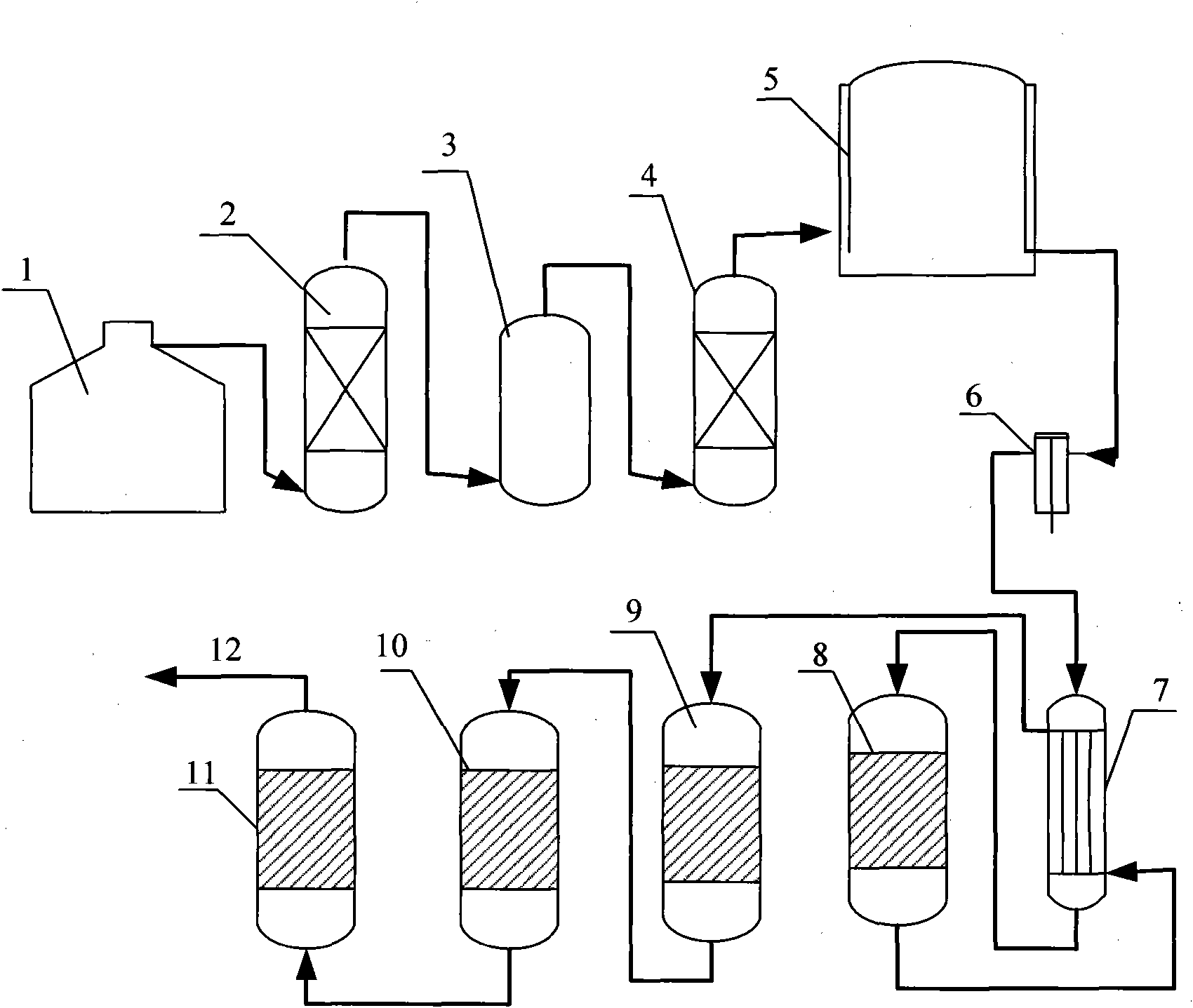
[0045] Embodiment 1: the process of producing ammonia synthesis gas from medium-capacity submerged arc furnace ferrosilicon alloy gas, see figure 2 .

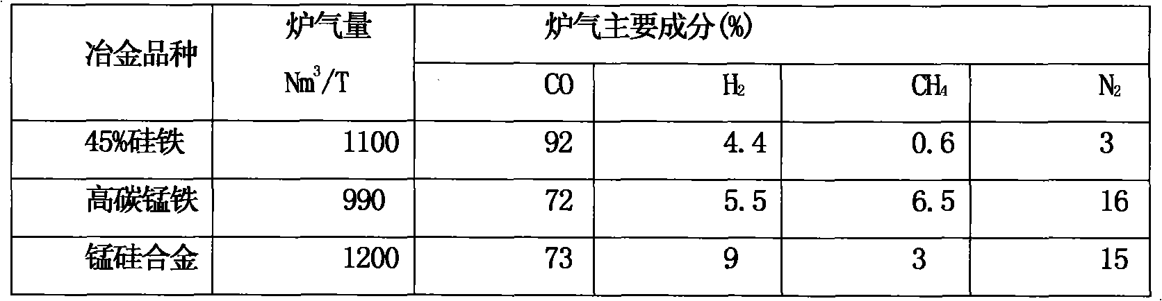
[0046] The 33000KVA submerged arc furnace produces 45% ferrosilicon alloy, with a daily output of 150 tons of ferrosilicon, and extracts 6800m of ferroalloy gas 3 / h, the recovery rate is 90%, and pure nitrogen is added 1790m 3 / h, ammonia production syngas 7730m 3 / h, synthetic ammonia 2.6 tons / h, with an annual output of 21,000 tons of synthetic ammonia.

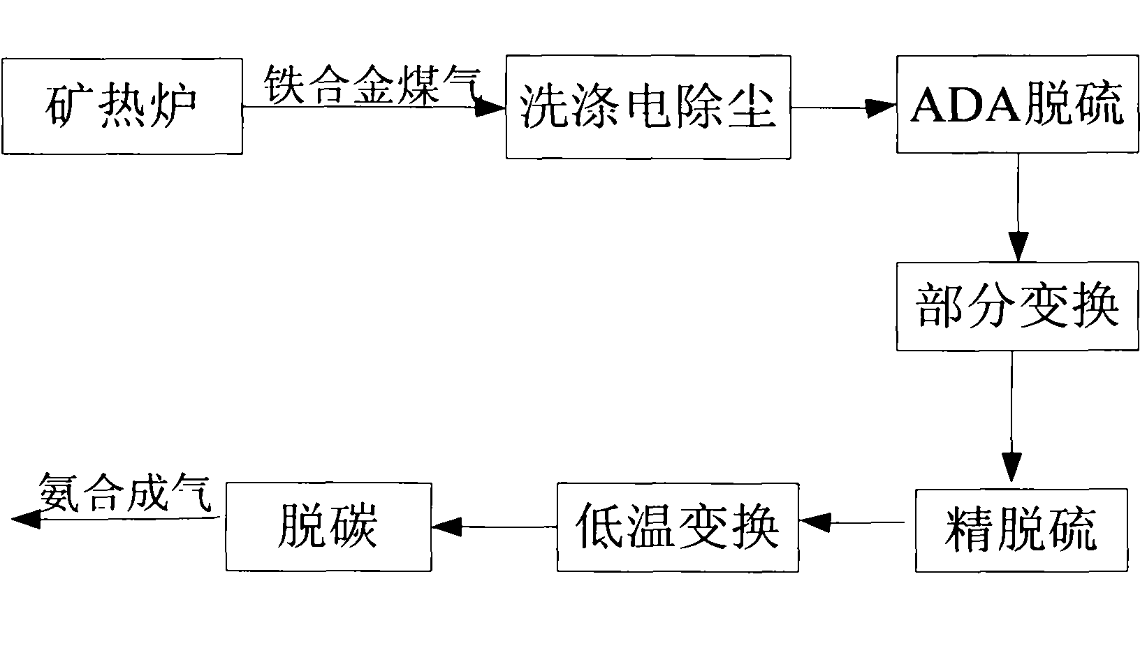
[0047] The ferroalloy gas is drawn from the top of the submerged arc furnace 1 and enters the washing and dust removal device 2. After dedusting and cooling, it enters the electrostatic precipitator 3 for further dust removal. After desulfurization by the desulfurization device 4, it enters the gas cabinet 5 to store and stabilize the components, and then is compressed by the gas compressor 6. When the temperature reaches 0.8mpa, it enters the shift gas heat exchanger 7...

Embodiment 2

[0048] Embodiment 2: the process of producing ammonia synthesis gas from large-capacity submerged arc furnace ferrosilicon alloy gas, see figure 2 .

[0049] The 105000KVA submerged arc furnace produces 45% ferrosilicon alloy, with a daily output of 500 tons of ferrosilicon, and extracts 30000m of ferroalloy gas 3 / h, the recovery rate is 90%, and pure nitrogen is added at 7900m 3 / h, ammonia production syngas 34900m 3 / h, 12 tons / h of synthetic ammonia, with an annual output of 95,000 tons of synthetic ammonia.

Embodiment 3

[0050] Embodiment 3: High carbon manganese ferroalloy gas produces ammonia synthesis gas flow process, see figure 2 .

[0051] The 33000KVA submerged arc furnace produces high carbon ferromanganese alloy, with a daily output of 150 tons of high carbon ferromanganese, and extracts 6200m of ferroalloy gas 3 / h, recovery rate 90%, add pure nitrogen 550m 3 / h, ammonia production syngas 6080m 3 / h, synthetic ammonia 2.0 tons / h, with an annual output of 16,000 tons of synthetic ammonia.


PUM


Abstract

The invention relates to a method for preparing ammonia synthesis gas from iron alloy smoke. The method comprises the following steps: carrying out scrubbing dust collection, desulfurization and nitrogen complement on the iron alloy smoke so as to ensure the ratio of nitrogen to carbon monoxide (CO) to hydrogen (H2) in the iron alloy smoke to achieve the requirement of the ammonia synthesis gas; converting the CO to the H2 through partial conversion and low temperature conversion; and removing carbon dioxide and trace CO in order to meet the requirement of the ammonia synthesis gas, thereby constituting an iron alloy-synthesis ammonia comprehensive utilization combo to achieve the purposes of energy conservation and emission reduction. By using the method, iron alloy and synthesis ammonia are produced to constitute the utilization combo, thereby shortening the synthesis ammonia process flow, improving the resource utilization rate, greatly lowering the cost, reducing the raw material transportation and gasification during ammonia synthesis, saving the investment, saving coke, coal and heavy oil consumed during ammonia synthesis and supplying short natural gas; and the economic benefits and energy conservation and emission reduction effects are obvious.

Description

technical field [0001] The invention relates to a method for producing ammonia synthesis gas from ferroalloy flue gas, which belongs to the field of comprehensive utilization of resources. Background technique [0002] Ferroalloy is one of the essential raw materials in the iron and steel industry. The essence of ferroalloy smelting is to use coke as a reducing agent to reduce the ore containing oxides to the elements required for ferroalloys, such as silicon, manganese, chromium, etc., and the reaction products remove metal elements. In addition, it is CO gas, which is easily discharged from the reaction zone. Ferroalloy smelting mostly adopts reduction electric furnace method, also known as submerged arc furnace method. In the past, the capacity of electric furnace was small, and open electric furnace and semi-closed electric furnace were used for production. And contains a lot of smoke and dust, polluting the environment. [0003] With the development of the iron and st...

Claims


Application Information

Patent Timeline
Patent Type & Authority Applications(China)
IPC IPC(8): C01B3/00C01B3/16C01B3/50C01B3/56C01C1/04
CPCY02E60/327Y02E60/32
Inventor 宁平殷在飞王学谦
Owner KUNMING UNIV OF SCI & TECH
Why Eureka
Try Eureka