Broadband reflecting mirror

A reflector and wide-band technology, applied in the field of wide-band reflectors, can solve the problems of warping of stress reflectors and a large number of laminated films, and achieve the effects of reducing the number, simplifying the manufacturing process, and efficient production

Inactive Publication Date: 2011-06-29
NIPPON ELECTRIC GLASS CO LTD
View PDF2 Cites 23 Cited by
  • Summary
  • Abstract
  • Description
  • Claims
  • Application Information

AI Technical Summary

Problems solved by technology

When using a dielectric mirror to reflect light in the wavelength range from 400nm to 2500nm, there is a problem that the number of laminated films must be very large
[0011] In addition, as the number of laminated films increases, there is a problem that the mirror warps due to the stress generated when the films are laminated.

Method used


Image

  • Broadband reflecting mirror
  • Broadband reflecting mirror
  • Broadband reflecting mirror

Examples


Embodiment 1

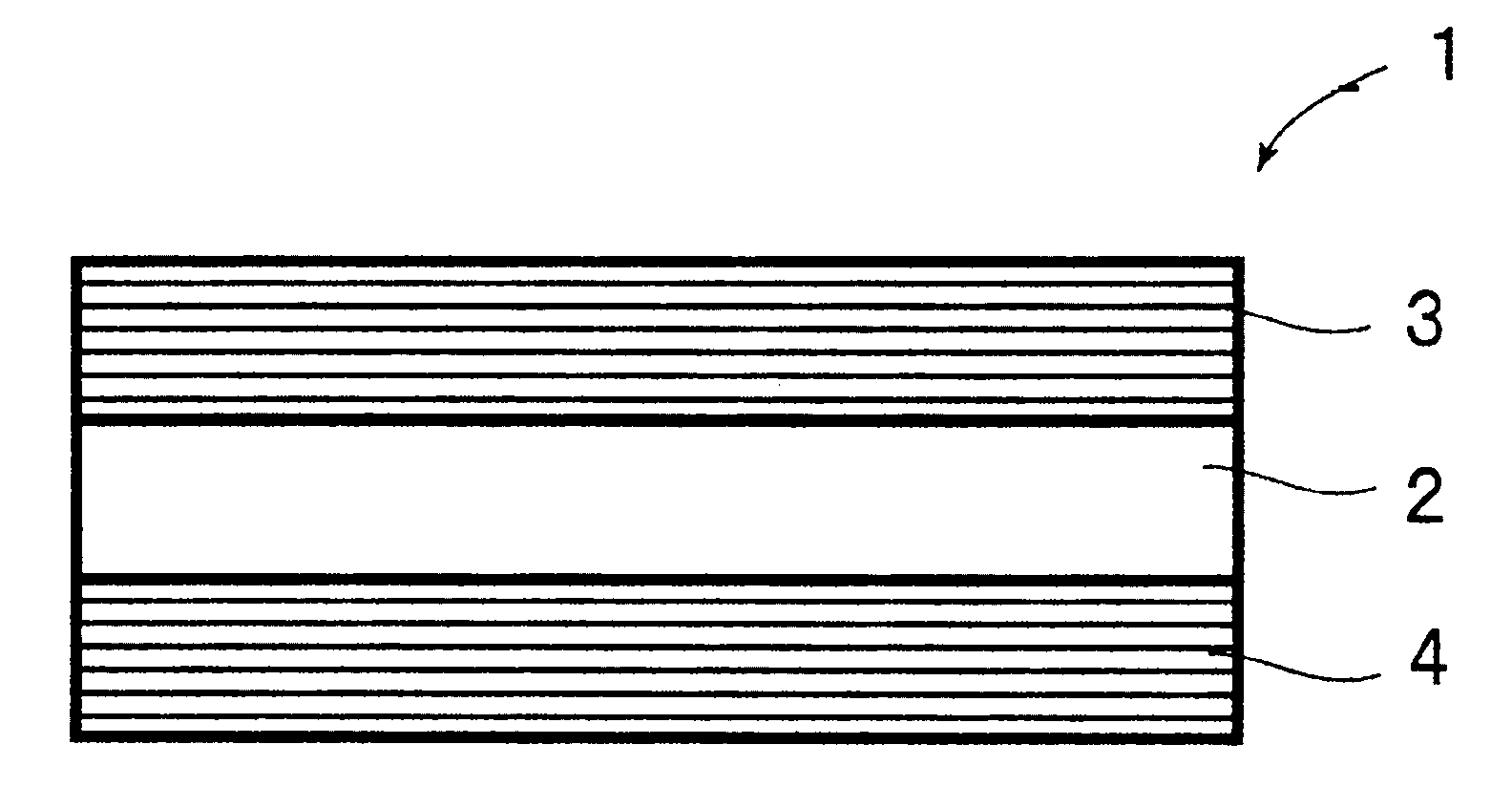
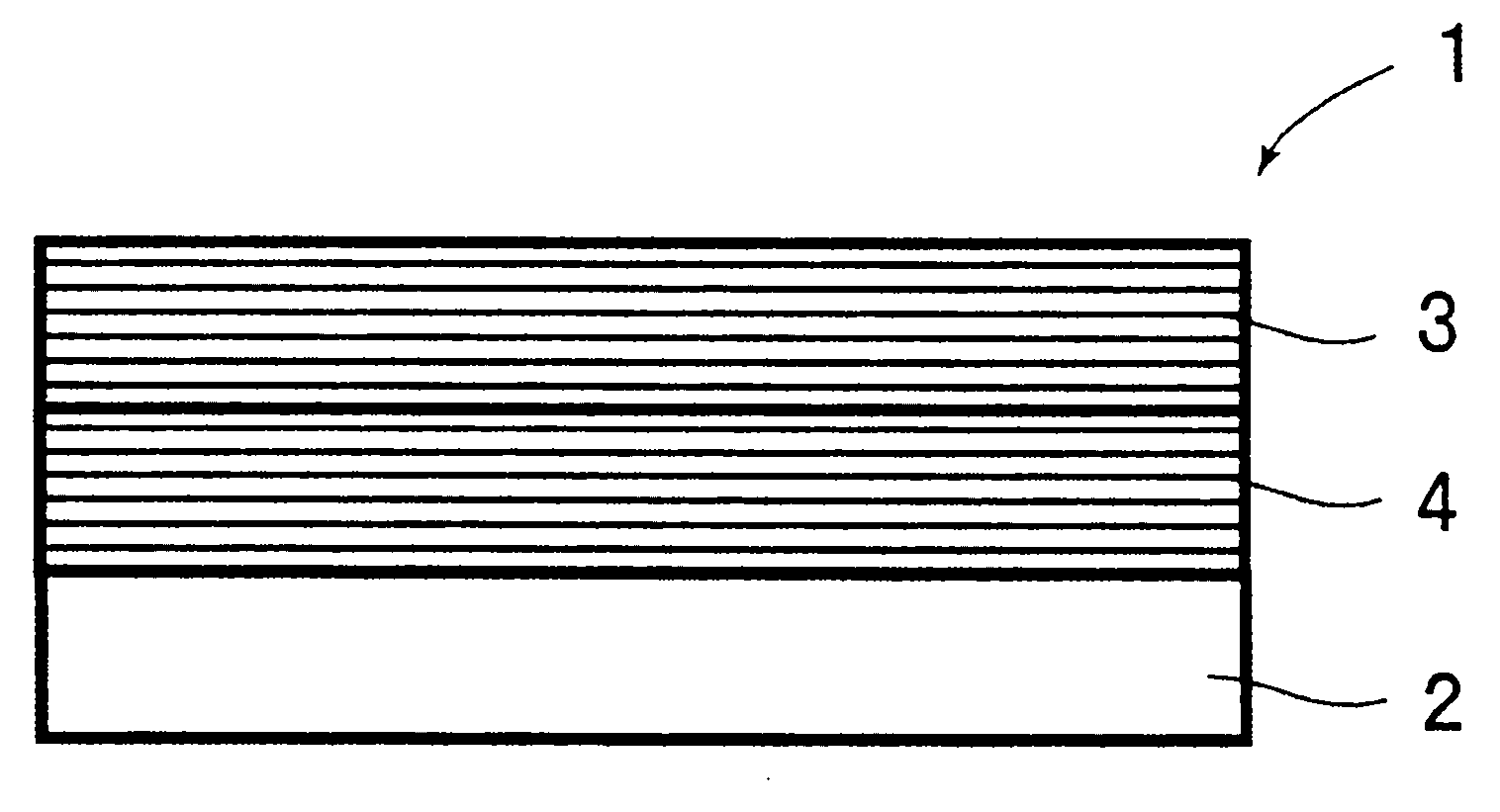
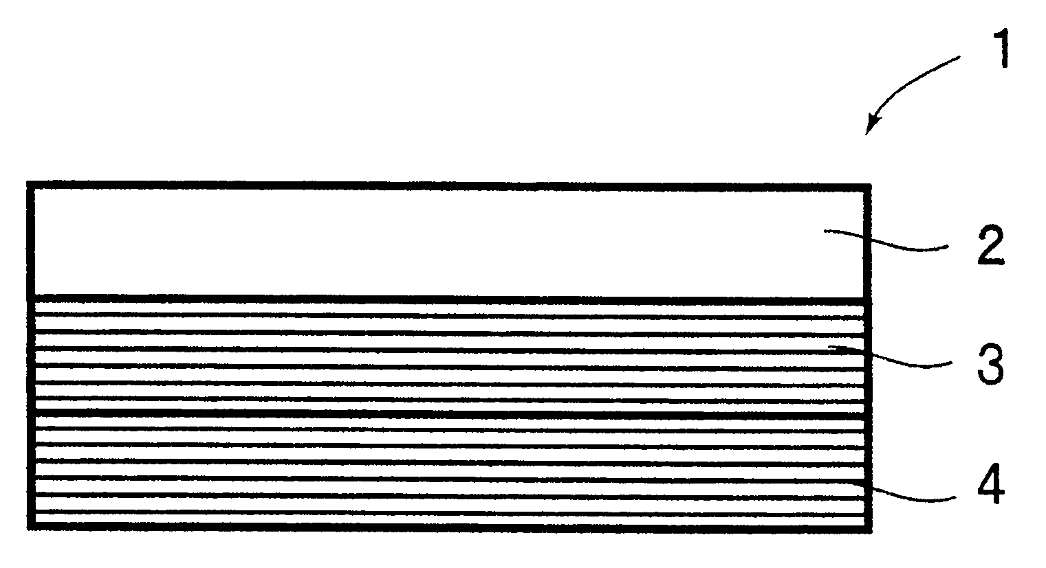
[0070] (Example 1) This example is an example of a broadband mirror in which a first reflective multilayer film is provided on one side of a glass substrate and a second reflective multilayer film is provided on the other side of the glass substrate. The glass substrate was manufactured by NEC Glass with a thickness of 0.3 mm, trade name: "OA-10". As the first high refractive index material layer of the first reflective laminate film, Nb 2 o 5 (Niobium pentoxide), as the first low refractive index material layer, use SiO 2 (silicon oxide). The film thickness and film structure of each layer are shown in Table 1. Layer No. in Table 1 is in order from the glass substrate side. As shown in Table 1, the number of layers of the first reflective multilayer film was 79.

[0071] The broadband mirror of this embodiment is a broadband mirror designed to exhibit the highest reflectance when the incident angle of light is about 20°.

[0072] 【Table 1】

[0073]

[0074] In the s...

Embodiment 2

[0093] (Example 2) The broadband mirror of this example is a broadband mirror that exhibits the highest reflectivity at an incident angle of about 16°.

[0094] As in Example 1, Nb was used as the first high refractive index material layer 2 o 5 , using SiO as the first low refractive index material layer 2 . Table 3 shows the film structure of the first reflective multilayer film.

[0095] 【table 3】

[0096]

[0097] In addition, in the present embodiment, the second reflective multilayer film can have the same film structure as that of the first embodiment. Therefore, the film structure shown in Table 2 is possible.

Embodiment 3

[0098] (Example 3) The broadband mirror of this example is a broadband mirror that exhibits the highest reflectivity at an incident angle of about 23°.

[0099] As in Example 1, Nb was used as the first high refractive index material layer 2 o 5 , using SiO as the first low refractive index material layer 2 . Table 4 shows the film structure of the first reflective multilayer film.

[0100] 【Table 4】

[0101]

[0102] In addition, in the present embodiment, the second reflective multilayer film can have the same film structure as that of the first embodiment. Therefore, the film structure shown in Table 2 is possible.


PUM


Abstract

Provided is a broadband reflecting mirror that has a high reflectance in the band with wavelengths ranging from 400nm to 2,500nm, heat resistance, and flaw resistance. A broadband reflecting mirror (1) for reflecting light in a band with wavelengths ranging from 400nm to 2,500nm, is provided with a first reflecting stacked film (3) in which a first high refractive index material layer and a firstlow refractive index material layer are stacked alternately to reflect light with a band on a short wavelength side in the band with wavelengths ranging from 400nm to 2,500nm, a second reflecting stacked film (4) in which a second high refractive index material layer and a second low refractive index material layer are stacked alternately to reflect light with a band on a long wavelength side in the band with wavelengths ranging from 400nm to 2,500nm, wherein the broadband reflecting mirror is characterized in that the first reflecting stacked film (3) is arranged on the incident side of the light, while the second reflecting stacked film (4) is arranged at a position from which the light penetrating the first stacked film (3) can be reflected, and wherein the first high refractive index material layer is formed of at least one material selected from the group consisting of niobium oxide, titanium oxide, zirconium oxide, tantalum oxide, hafnium oxide, silicon nitride, yttrium oxide and indium tin oxide, the first low refractive index material layer is formed of at least one material selected from the group consisting of silicon oxide and magnesium fluoride, the second high refractive index material layer is formed of at least one material selected from the group consisting of silicon and germanium, and the second low refractive index material layer is formed of at least one material selected from the group consisting of silicon oxide and magnesium fluoride.

Description

technical field [0001] The invention relates to a wide-band reflector for reflecting light in the wavelength range of 400nm to 2500nm. Background technique [0002] Recently, attention has been paid to devices and systems utilizing thermal energy obtained by concentrating sunlight, and development and practical use of solar heat collectors and solar concentrating systems have been proceeding. [0003] For example, research is being conducted on solar thermal power generation systems that concentrate sunlight and use the heat energy to generate high-temperature and high-pressure steam, and use this steam to drive turbines. [0004] As a solar concentrating system, there is known a system in which a plurality of heliostats are installed on the ground, and the reflected light from the heliostats is reflected by a concentrating reflector to concentrate sunlight on a heat collector (Non-Patent Document 1 Wait). [0005] In order to utilize the thermal energy of sunlight, it is ...

Claims


Application Information

Patent Timeline
Patent Type & Authority Applications(China)
IPC IPC(8): G02B5/08F24J2/10G02B5/26G02B5/28F24S23/70F24S23/77F24S23/79
CPCF24J2002/1071Y02E10/40G02B5/0825F24J2/16F24J2/1057F24J2/18F24S23/79F24S2023/86F24S23/82F24S23/77
Inventor 金井敏正樱井武
Owner NIPPON ELECTRIC GLASS CO LTD
Why Eureka
Try Eureka