Elliptical light spot optical fiber collimator

An optical fiber collimator and elliptical light spot technology, which is applied in the field of optical communication devices and optical fiber sensing, can solve problems such as the difficulty of microlens processing technology, and achieve the effects of easy expansion of the number of optical fibers, simple structure, and mature manufacturing process.

Inactive Publication Date: 2011-09-14
SHANGHAI INST OF MICROSYSTEM & INFORMATION TECH CHINESE ACAD OF SCI
View PDF8 Cites 16 Cited by
  • Summary
  • Abstract
  • Description
  • Claims
  • Application Information

AI Technical Summary

Problems solved by technology

However, the diameter of G-lens or C-lens used in the field of optical communication and optical fiber sensing is usually between 1.0mm and 2.2mm. It is necessary to process the curvature of the tiny end faces of these lenses with precise controllability and the central axis and micro The cylindrical surface whose optical axis of the lens intersects vertically still has great difficulty in the microlens processing technology

Method used


Image

  • Elliptical light spot optical fiber collimator
  • Elliptical light spot optical fiber collimator
  • Elliptical light spot optical fiber collimator

Examples


Embodiment 1

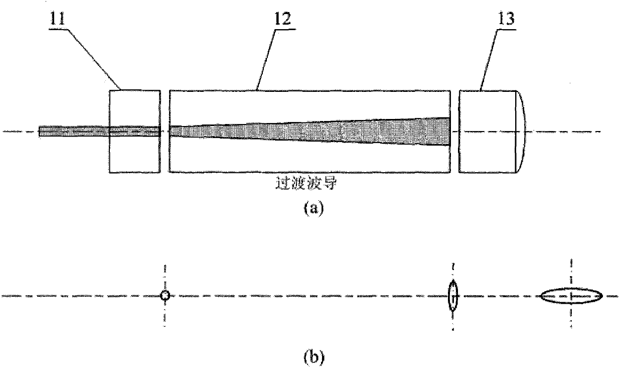
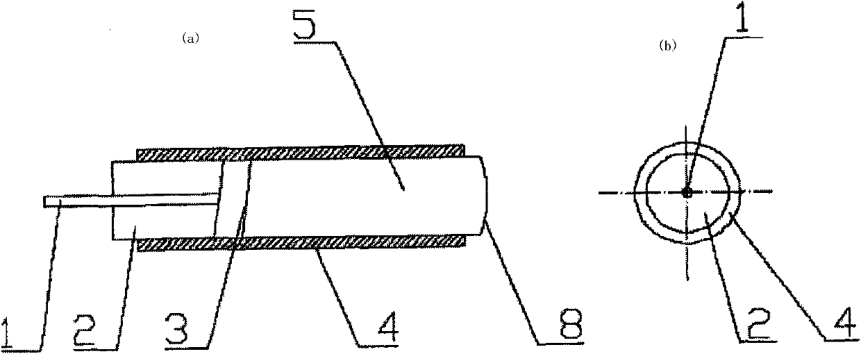
[0014] Single Fiber Elliptical Spot Fiber Collimator: Refer to image 3 (a), use the planar optical waveguide technology to manufacture, scribe, and polish the end face to obtain the planar optical waveguide converter, in which there is at least one transitional waveguide, select the single-core optical fiber and the transitional waveguide of the planar optical waveguide converter for optical coupling, adjust the two The relative distance and angle of the end faces until the transmission light loss from the optical fiber to the waveguide is the lowest, and the two are fixed with glue as an integral end, and then the optical path between the end and the collimating microlens is adjusted and fixed. Methods According to the conventional circular spot single-fiber collimator transmission application coupling method. The two opposite end faces of the optical fiber head and the planar optical waveguide converter, as well as the two opposite end faces of the planar optical waveguide ...

Embodiment 2

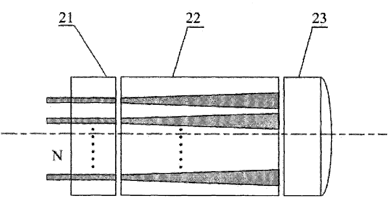
[0016] According to the single-fiber elliptical-spot fiber collimator structure of the present invention, it is easy to think of adopting a double-core or linearly arranged multi-core fiber head or a one-dimensional fiber array to realize a dual-fiber elliptical-spot collimator and a multi-fiber elliptical-spot collimator. refer to Figure 4 , the optical fiber head adopts a double-core or linearly arranged multi-core optical fiber head or a one-dimensional optical fiber array, the number of optical fibers is N≥2, the planar optical waveguide converter is made by planar optical waveguide technology, obtained by scribing and end-face polishing, and the number of transitional waveguides≥ N, the minimum distance between the transitional waveguides meets the requirements of the on-chip crosstalk index, and the geometric aperture of the collimating microlens meets the aberration requirements of N parallel optical paths. The packaging process is as follows: first complete the optica...


PUM


Abstract

The invention relates to an elliptical light spot optical fiber collimator, which is characterized by consisting of three parts through coupling in turn, namely an optical fiber head 11, a planar optical waveguide transducer 12 and a collimating micro-lens 13, wherein the planar optical waveguide transducer 12 widens or compresses a waveguide in a width or thickness direction through a transitional waveguide, and circular mode field light spots output through a single mode fiber are coupled to enter the planar optical waveguide transducer, are transmitted through the transitional waveguide and converted into elliptical mode field light spots, and pass through the collimating micro-lens to form elliptical light spot collimating beams. The elliptical light spot optical fiber collimator has a key component of the planar optical waveguide transducer, can be manufactured in batch by a mature planar waveguide process, and is low in cost and easy to implement. An optical switch or an attenuator is manufactured from the elliptical light spot optical fiber collimator and the micro-lens, so that the moving direction of the translational micro-lens is consistent with the short axis direction of the elliptical light spots, and the requirement on the travel of the micro-lens can be greatly reduced.

Description

technical field [0001] The invention relates to an elliptical spot optical fiber collimator, more precisely provides an elliptical spot optical fiber collimator using a planar light waveguide converter, which belongs to the field of optical communication devices and optical fiber sensing. Background technique [0002] With the development of Micro-Opto-Electro-Mechanical Systems (MOEMS) technology, Micro-Electro-Mechanical Systems (MEMS) optical devices are gradually being applied to the fields of optical communication and optical fiber sensing. MEMS optical devices have attracted more and more attention due to their advantages of mass production, low cost, small size, low power consumption, and high speed. The coupling between the MEMS optical device and the optical fiber mostly adopts the collimator coupling method, because compared with the direct coupling method, the collimator coupling can achieve smaller insertion loss and larger working distance. Most of the current ...

Claims


Application Information

Patent Timeline
Patent Type & Authority Applications(China)
IPC IPC(8): G02B6/32G02B6/26G02B6/14
Inventor 吴亚明徐静黄占喜
Owner SHANGHAI INST OF MICROSYSTEM & INFORMATION TECH CHINESE ACAD OF SCI
Why Eureka
Try Eureka