All optical wavelength converter and all optical wavelength conversion method for dual-semiconductor optical amplifier structure

An all-optical wavelength conversion and wavelength converter technology, used in optical demodulation, optics, instruments, etc., can solve problems such as unfavorable large-scale engineering applications and later system maintenance, high price, complex system structure, etc., and achieve low-cost operation. Maintenance cost, simplifying network structure, ensuring the effect of operation and maintenance cost

Active Publication Date: 2011-11-02
WUHAN POST & TELECOMM RES INST CO LTD
View PDF2 Cites 9 Cited by
  • Summary
  • Abstract
  • Description
  • Claims
  • Application Information

AI Technical Summary

Problems solved by technology

One is to use a specific wavelength to detect optical lasers inside the remote all-optical wavelength conversion module. Since the conversion wavelength corresponds to the wavelength of the laser one-to-one, it is necessary to produce and maintain all-optical wavelength conversion modules of different wavelength models, which is not conducive to large-scale Engineering application and post-system maintenance
The other is to use a multi-wavelength detection light so...

Method used


Image

  • All optical wavelength converter and all optical wavelength conversion method for dual-semiconductor optical amplifier structure
  • All optical wavelength converter and all optical wavelength conversion method for dual-semiconductor optical amplifier structure
  • All optical wavelength converter and all optical wavelength conversion method for dual-semiconductor optical amplifier structure

Examples


Embodiment Construction

[0021] The present invention will be described in further detail below in conjunction with the accompanying drawings and embodiments.

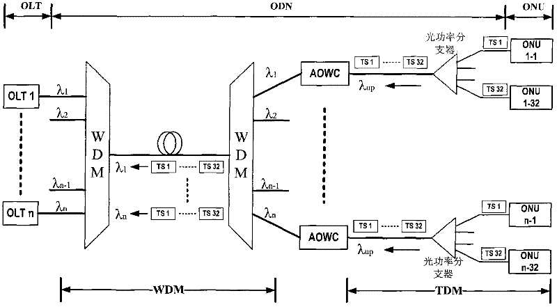
[0022] Such as figure 1 As shown, it is a structural block diagram of the hybrid wavelength division time division multiplexing passive optical network system. Multiple TDM-PON OLT central offices are placed at the network convergence point / central computer room. The downlink data in this device is optically modulated with a specific wavelength and outputs different optical wavelengths (λ 1 , lambda 2 ...λ n-1 , lambda n ), to distinguish each OLT, the downlink signal light of OLT with different wavelengths is multiplexed into one optical fiber for downlink transmission through WDM devices. At the remote node of the optical link, the WDM device is also used to demultiplex the optical wavelength signal of each branch (λ 1 , lambda 2 ...λ n-1 , lambda n ), and then transmitted to each ONU through the optical power splitter. For each ONU...


PUM


Abstract

The invention provides an all optical wavelength converter and all optical wavelength conversion method for a dual-semiconductor optical amplifier structure and relates to a hybrid wavelength division time division multiplex passive optical network system. A downlink signal light can be divided into two paths through a 1:2 optical splitter, i.e., one path of light is compensated by an erbium-doped fiber amplifier (EDFA), combined by a wavelength division multiplexer and then sent to a user terminal; the other path of light successively passes through the EDFA, a first semiconductor optical amplifier and an adjustable optical attenuator and then is used for the probe light input of a cross-gain modulation structure; after being divided by the wavelength division multiplexer, an uplink signal light is successively connected with the EDFA, the adjustable optical attenuator and a polarization controller and is used for the pump light input of the cross-gain modulation structure; and the probe light and the pump light can be input into an optical coupler, converted through a second semiconductor optical amplifier and a band pass filter and then output. The all optical wavelength converter and the all optical wavelength conversion method are in accordance with the optical passive and colorless requirements; and meanwhile, the all optical wavelength converter has a simple system structure, thus reducing the operation and maintenance costs of the system and being beneficial to the application and later maintenance for large-scale projects.

Description

technical field [0001] The invention relates to a hybrid wavelength division time division multiplexing passive optical network system, specifically an all-optical wavelength converter with a double semiconductor optical amplifier structure and a conversion method. Background technique [0002] "Fiber into copper and out of copper" is the general trend of the future development of the access layer network. Broadband fiber-to-the-home technology is gradually replacing various traditional narrowband copper cable access technologies and has become the first choice of fixed network operators. The passive optical network (Passive Optical Network, PON) stands out from various optical fiber access technologies with its own advantages of large capacity, full service, low cost, high reliability, and easy maintenance. The current mainstream passive optical network technology is divided into two types: wavelength division multiplexing passive optical network (WDM-PON) and time division...

Claims


Application Information

Patent Timeline
IPC IPC(8): G02F2/00H04J14/02
Inventor 何炜杨铸刘武张晓吟
Owner WUHAN POST & TELECOMM RES INST CO LTD
Why Eureka
Try Eureka