Alignment detection device for photoetching equipment

A detection device and reference plate technology, applied in the field of lithography, can solve problems such as difficult assembly of blind holes and photon conversion crystals, difficulty in processing and manufacturing blind holes in quartz plates, crosstalk of transmitted optical signals, etc., to prevent crosstalk between transmitted light signals, The effect of improving the convenience of assembly without reducing the assembly accuracy

Active Publication Date: 2011-11-23
SHANGHAI MICRO ELECTRONICS EQUIP (GRP) CO LTD +1
View PDF7 Cites 5 Cited by
  • Summary
  • Abstract
  • Description
  • Claims
  • Application Information

AI Technical Summary

Problems solved by technology

The distance from the bottom surface of the blind hole of the reference plate to the upper surface of the wafer stage reference plate in the prior art does not exceed 1 mm, for example, 0.5 mm. The more serious the crosstalk between signals, the difficulty of the existing processing technology lies in the processing and manufacturing of the blind hole of the reference plate. The blind hole of the quartz plate is difficult to manufacture, and the blind hole and the photon conversion crystal are difficult to assemble. There is a gap between the transmitted optical signals generated by each branch of the mark. crosstalk

Method used


Image

  • Alignment detection device for photoetching equipment
  • Alignment detection device for photoetching equipment
  • Alignment detection device for photoetching equipment

Examples


Embodiment Construction

[0029] In the following, preferred embodiments according to the present invention will be described in detail with reference to the accompanying drawings.

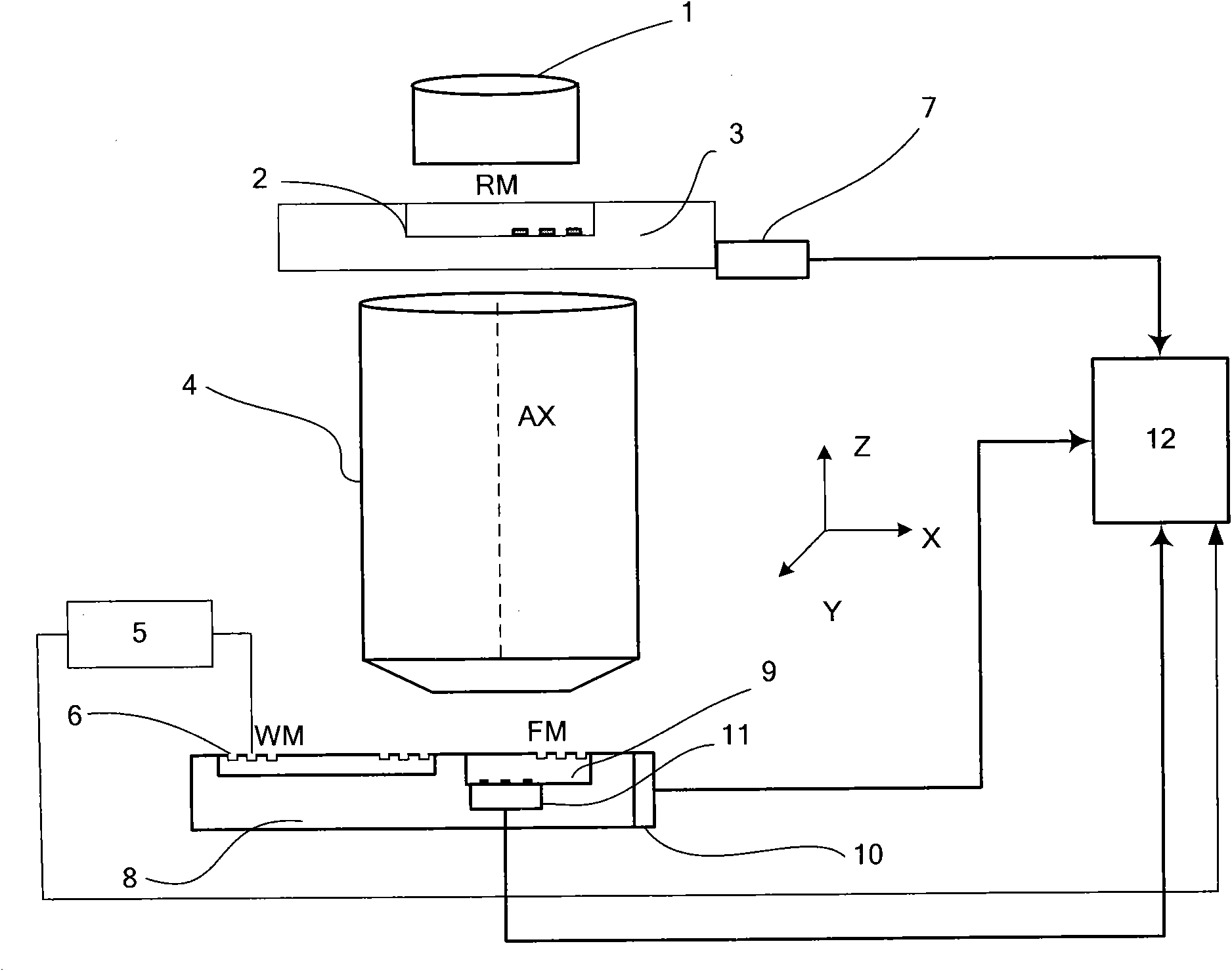
[0030] figure 2 Shown is a schematic structural diagram of the overall layout and working principle between the alignment device for lithography equipment and the lithography equipment according to the present invention. As shown in the figure, the composition of the lithography equipment includes: an illumination system 1 for providing an exposure beam; a mask support and a mask table 3 for supporting a reticle 2, which has a mask pattern and a periodic A mask alignment mark RM of the structure; a projection optical system 4 for projecting a mask pattern on a reticle 2 onto a wafer 6; a wafer holder for supporting the wafer 6 and a wafer stage 8 engraved with The reference plate 9 of the fiducial mark FM (including the reflective mark for wafer stage alignment and the transmissive mark for mask alignment), the alignment...


PUM


Abstract

The invention relates to an alignment detection device for photoetching equipment. The device comprises a wafer stage reference board, the lower surface of which is provided with a transmission type mark for mask alignment; a photon conversion crystal, the center of which is aligned with the center of the corresponding transmission type mark, for converting ultraviolet light into visible light; an optical support for installing the photon conversion crystal; an isolation board for isolating light propagation and an external heat source; an optical filter installed on the isolation board for filtering useless light beyond the visible light band; and a fiber directly connected to the optical filter.

Description

technical field [0001] The invention relates to the field of lithography, in particular to an alignment detection device for lithography equipment. Background technique [0002] In industrial installations, due to the need for high precision and high productivity, there are a large number of measurement systems and control systems for precision photoelectric measurement, high-speed real-time signal sampling, data acquisition, data exchange, and communication transmission. These systems require us to use various methods to realize the control of sensor signal sampling control, data acquisition control, data exchange control and data transmission communication. Devices that require this measurement and control include: integrated circuit manufacturing lithography devices, liquid crystal panel lithography devices, MEMS / MOEMS lithography devices, advanced packaging lithography devices, printed circuit board lithography devices, printed circuit board processing devices, and print...

Claims


Application Information

Patent Timeline
Patent Type & Authority Applications(China)
IPC IPC(8): G03F7/20G03F9/00
Inventor 戈亚萍杜聚有徐荣伟
Owner SHANGHAI MICRO ELECTRONICS EQUIP (GRP) CO LTD
Why Eureka
Try Eureka