
A kind of micro-torsion mirror with trench isolation mirror surface and its manufacturing method

A technology of micro-torsion mirror and trench isolation, which is applied in the process of producing decorative surface effects, micro-structure technology, micro-structure devices, etc., can solve the problems of difficulty in implementation, complex design, and complex system implementation, and achieve reliable performance. The effect of guaranteeing stability and accuracy, novel design methods, and broad market prospects

Active Publication Date: 2011-12-07
XIAN LEADMEMS MICROSYST TECH CO LTD
View PDF5 Cites 12 Cited by
  • Summary
  • Abstract
  • Description
  • Claims
  • Application Information

AI Technical Summary

Problems solved by technology

[0005] In 1999, Cornell University used surface technology combined with deep reactive ion etching (DRIE) bulk silicon technology to produce a Staggered Vertical Comb (SVC) micro-torsion mirror. The rotation angle was only 1.1° under 18V voltage drive, but this research opened up In 2000, the University of California, Berkeley developed the SVC micro-torsion mirror based on the silicon-silicon bonding process. Driven by AC voltage, its scanning angle reached 24.9°; in 2002, the University of California The PR.Patterson research group of the University of Los Angeles proposed that the Angular Vertical Comb (AVC) driver can effectively improve the static angle of the micro-torsion mirror, but its AVC is made of a photoresist hinge, and the process is poor in operability; these reported micro-torsion mirrors are all Working under open-loop control, it is greatly affected by the outside world. In order to better realize the stable rotation of the torsion mirror, it is generally closed-loop control by detecting the change of capacitance to feedback information.
In the document "Driver ASIC for synchronized excitation of resonant micromirrors", Roscher, K. et al. used a special integrated circuit design to implement closed-loop control of the detection of capacitance changes, but often the signal of this capacitance is very weak, and the light The detection technology requires higher precision, so this method is very difficult to implement; in 2010, A. Tortschanoff et al. proposed in the document "Optical Position Feedback and Phase Control of MOEMS-Scanner Mirrors", by using laser beams in the The back reflection of the mirror, plus a high-speed photodetector to quickly detect the reflection of light and determine the parameters to realize the closed-loop control of the system, but this method needs to add a high-speed photodetector and a trigger diode to achieve, so that the design of the entire system become more complex and cost more
[0006] To sum up, in order to achieve a more stable operation of the micro-torsion mirror, capacitive detection is generally used to achieve closed-loop control, but the existing methods have problems such as weak feedback signal, complex system implementation, and low accuracy.
If the capacitance of the mirror comb is directly detected, when the anchor point connected to the mirror and the anchor point of the fixed comb end are connected to the driving voltage, if it is used as the two ends of the capacitance signal detection, the driving signal and the detection signal will be aliased, which will not be accurate. Realize the measurement of the capacitance between the comb teeth after voltage is applied, so that the closed-loop control of the micro-torsion mirror cannot be realized

Method used


Image

  • A kind of micro-torsion mirror with trench isolation mirror surface and its manufacturing method
  • A kind of micro-torsion mirror with trench isolation mirror surface and its manufacturing method
  • A kind of micro-torsion mirror with trench isolation mirror surface and its manufacturing method

Examples


Embodiment Construction

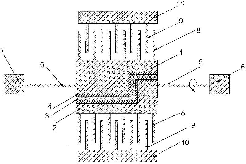
[0024] The micro-torsion mirror with grooves and mirrors in this embodiment includes a mirror, which is characterized in that the mirror is composed of a conductive mirror 1 and an isolation mirror 2 isolated by the groove; the conductive mirror 1 and the isolation mirror 2 are respectively Through a support beam 5, it is respectively connected with the power lead anchor point 7 and the test lead anchor point 6, so that the whole mirror is supported and suspended in the middle of the two anchor points by the support beam 5; Silicon 4, filled with a sandwich material of polysilicon 3 in the middle, the function of the silicon dioxide layer 4 is to insulate the mirrors, and the filled polysilicon 3 plays a role of mechanical connection to the two separated conductive mirrors 1 and isolation mirrors 2 Movable comb teeth 8 are arranged on the conductive mirror surface 1, and the fixed comb teeth 9 fixed on the fixed anchor point 11 of the energized lead wire form a pair of driving ...


PUM


Abstract

The invention discloses a micro torsion mirror with a trench-isolated mirror surface and manufacturing method thereof, and belongs to the field of micro-opto-electric mechanical systems (MOEMS). The mirror surface of the micro torsion mirror consists of a conductive mirror surface 1 isolated by a trench and an isolating mirror surface 2; the trench is filled with a sandwiched material with carbon dioxide 4 at two sides and polycrystalline silicon 3 in the middle. When the micro torsion mirror is in work, after an energized lead anchor 7 is energized, the conductive mirror surface 1 and the movable comb teeth 8 on the conductive mirror surface 1 are energized to drive the comb teeth to drive the whole mirror surface to rotate under the action of electrostatic force; due to the existence of the trench, the isolating mirror surface 2 is nonconductive; therefore, an accurate capacitance value caused by the rotation of the mirror surface can be obtained by detecting the comb teeth in an uncharged manner. The whole apparatus has the advantages of simple structure, novel design method and obvious effect, and can effectively measure the capacitance between the movable comb teeth and the fixed comb teeth and well realize the closed-loop control of the system, therefore, the reliability and accuracy of the performance of the micro torsion mirror can be guaranteed; the micro torsion mirror has wider market prospect.

Description

[0001] Field [0002] The invention belongs to the field of micro-opto-electromechanical systems (MOEMS), and mainly relates to a micro-torsion mirror and a manufacturing method thereof. Background technique [0003] Compared with traditional beam deflection elements, micro-torsion mirrors have the advantages of low energy consumption, miniaturization, and easy integration. In addition, their applications in communications, consumer electronics, biomedicine, military defense, and other fields continue to expand, and they have gradually become a research topic in the field of optical MEMS. hotspots. The electrostatic comb-driven micro-torsional mirror has the characteristics of simple structure, high unit energy density, and large rotation angle. It is one of the most commercially promising micro-torsional mirror forms in the future. [0004] In view of the broad commercial prospects of micro-torsional mirrors, especially the vertical comb-driven micro-torsional mirrors based ...

Claims


Application Information

Patent Timeline
Patent Type & Authority Applications(China)
IPC IPC(8): G02B26/08B81C1/00
Inventor 乔大勇康宝鹏燕斌刘耀波
Owner XIAN LEADMEMS MICROSYST TECH CO LTD
Learn More