A microfluidic chip for pcr and a real-time pcr virus rapid detection device

A technology of microfluidic chips and microfluidic channels, applied in enzymology/microbiology devices, biochemical cleaning devices, specific-purpose bioreactors/fermenters, etc., which can solve the slow heating and cooling speed and the demand for reactants Large volume, high sample consumption, etc., to achieve the effect of less sample consumption, fast detection speed, and integrated operation

Inactive Publication Date: 2011-12-21
HEFEI INSTITUTES OF PHYSICAL SCIENCE - CHINESE ACAD OF SCI
View PDF5 Cites 53 Cited by
  • Summary
  • Abstract
  • Description
  • Claims
  • Application Information

AI Technical Summary

Problems solved by technology

[0006] Traditional PCR amplification instruments have disadvantages such as large heat capacity, slow heating and cooling speed, and high sample consumption
It usually takes several hours to complete an amplification process, and the demand for reagents is high

Method used


Image

  • A microfluidic chip for pcr and a real-time pcr virus rapid detection device
  • A microfluidic chip for pcr and a real-time pcr virus rapid detection device
  • A microfluidic chip for pcr and a real-time pcr virus rapid detection device

Examples


Embodiment 1

[0035] Example 1: Fabrication of a three-layer PDMS microfluidic chip

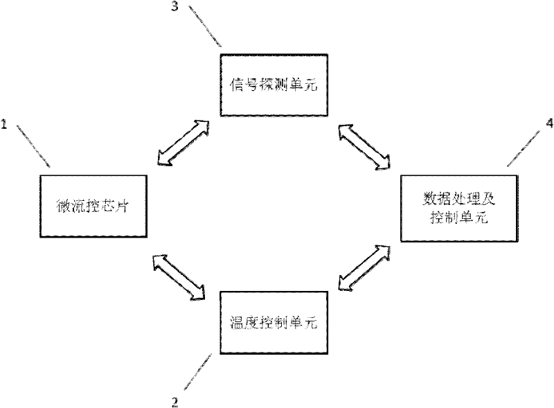
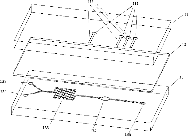
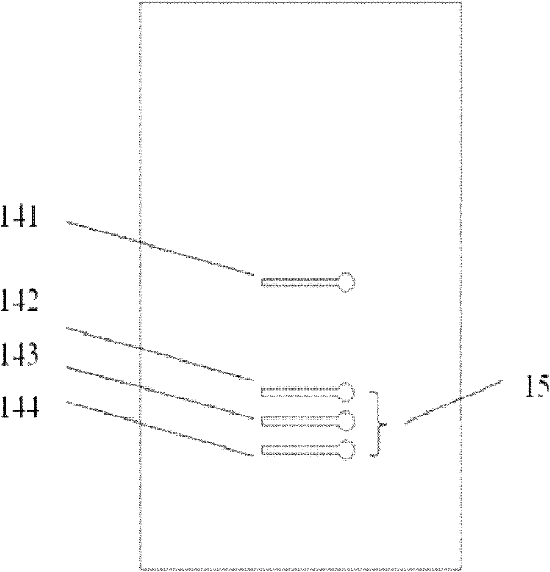
[0036] The microfluidic chip is formed by reversibly sealing the upper control channel 11 , the middle PDMS film layer 12 and the lower microfluidic channel layer 13 . The thickness of the PDMS film is 100um, the width and depth of the microfluidic channel are 100um and 75um respectively, and the width and depth of the gas path control channel are 200um and 75um respectively. The microfluidic chip is aligned and sealed under a microscope in the clean room, and the microvalves 141 , 142 , 143 , 144 and the micropump 15 are guaranteed to work normally. The function of driving the microfluid is realized by controlling the opening and closing of the three microvalves 142, 143, 144 constituting the micropump 15 through the data processing and control unit 4, Image 6 It is a picture of the opening and closing of the microvalve taken under the microscope. The picture on the left is the picture of the upper gas ...

Embodiment 2

[0037] Example 2: Detection of fluorescence signal of fluorescein isothiocyanate (FITC) in the channel of microfluidic chip

[0038] The sample to be tested with fluorescein isothiocyanate (FITC) is injected into the microfluidic chip 1 from the sample inlet 131, 132, and the data processing and control unit 4 controls the three microvalves 142, 143 in the micropump 15 , 144 are sequentially opened or closed to drive the sample to flow into the micro-mixer 133. After being fully mixed in the micro-mixer 133, the sample enters the PCR reaction chamber 134, and the data processing and control unit 4 issues an order to open the signal detection unit 3, and the signal detection unit The excitation light source 31 in 3 emits excitation light, and irradiates the PCR reaction chamber 134 through the optical transmission unit 32. Under the irradiation of the excitation light of 480 nm, the FITC will generate fluorescence with a center wavelength of 520 nm, which is still collected by t...


PUM


Abstract

The invention relates to a microfluidic control chip which is formed by bonding and sealing PDMS (Polydimethylsiloxane) material integrated with a micro valve, and comprises an upper layer of air control passage, a middle layer of PDMS membrane and a lower layer of microfluidic passage. A real-time PCR virus quick detection device comprises the microfluidic control chip, a temperature control unit, a signal detection unit and a data processing and control unit. The invention designs the microfluidic control chip which is integrated with the micro valve, is in a three-layer PDMS structure, andis used for virus detection and the real-time fluorescent PCR detection device. Compared with the traditional method, the invention has the advantages of short time, less sample usage, quick detection speed, simpleness and convenience in operation, integration and the like.

Description

technical field [0001] The invention relates to a microfluidic chip for realizing polymerase chain reaction (Polymerase Chain Reaction, PCR) and a virus rapid detection device for real-time PCR. Background technique [0002] Since the concept of micro-total analysis system was proposed in 1990, microfluidic chip technology has opened up a broad space for development in the fields of chemistry, life science, environmental science and food science. Based on microfluidic control technology, microfluidic chip technology guides the development of analytical instruments in the direction of miniaturization, integration, automation, and high-throughput rapid quantitative analysis, providing a possibility for real-time detection and on-site analysis of biochemical environmental samples. strategy, which has broad market prospects in medical diagnosis and epidemic monitoring in agricultural breeding systems. [0003] Polymerase chain reaction (Polymease Chain Reaction, PCR), also know...

Claims


Application Information

Patent Timeline
Patent Type & Authority Applications(China)
IPC IPC(8): C12M1/00C12M1/38C12M1/36C12M1/34
Inventor 朱灵刘勇张龙张弓王贻坤李志刚
Owner HEFEI INSTITUTES OF PHYSICAL SCIENCE - CHINESE ACAD OF SCI
Why Eureka
Try Eureka